1K resistors
Nordic,
Another idea on dropping the power drop across these. Try a little higher voltage zener. I tried from 11.9 up to 17.2 volt. Settled at around 15.4. When raising this up the power drop comes down. A power supply and current limiting resistor is needed to match up the zeners, they usually are +/- 5% from rated votlage. In my mind, the LM318 benefits if feed with exactly the same rail voltages.
Latest one I built uses two 12 volt SLA batteries. This gives 13.2 volts or so. It was needed to get the Monos up to four chassis. Hated to have less chassis than the ASR Emitter II.
Finished stuffing the circuit board for the Evolution a week ago. Went with the full version, 80,000 of ufd filter caps, and parallel LM3886 current pumps. The tough part, drilling a chassis is next.
Hope it will tame the thumpers in my new speakers. I am moving from 100 dB horns to some ported boxes flat to 20 Hz. They are underdamped, and need lots of current and low output impedance to provide control.
George
Will keep that in mind, was going to swap the 12v zeners for 2 6v zeners in series due to the lower zener noise.
This is very interesting & long thread. It is not practically possible go through. Hence it is my request that someone should put a concluding part here. It must be with final schematics, PCB & BOM. This will be very useful for newcomers like me.
Nordic said:Will keep that in mind, was going to swap the 12v zeners for 2 6v zeners in series due to the lower zener noise.
according to research done elsewhere here this would not be a good idea.
the most noisy zeners where those around 6V
at around 12V and over it was found that it is best to go for a single zener.
below 12V multiples of LED's was better
zeners below about 4V where also ok
a search on "zener noise" using google in diyaudio.com will find all the details
mike ... 🙂
Nordic,
Mills non-inductive Ik,5W are small for their rating, and will fit, if that appeals to you. I'll use them on my next rev c pcb.
protos,
The Denon DL103 is a nice sounding cartridge, but it's conical stylus has not the transparency and detail retrival of the finer profile stylii.
re. Evolution,
I've made a start, but have been interrupted by necessary home maintenance chores. I have the 3mm anodised panels cut, ready for drilling etc. Also have the locally grown African Mahogany front panel finished, ready for bolting directly onto the heatsinks.
I simply gave it 5 coats of boiled linseed oil at intervals of 2 days, then two coats of clear beeswax and canauba wax polish - looks nice. I should be back to the Evolution in a week. I would prefer to build the full version , but will start with the base version, as that is what Mauro wants me to try out first.
Audie.
Hi there guys,
Finally I have some spare time to start my Rev C build...
In considering the logistics of what's needed (phono stage etc.) I've been wondering; is there anything to be gained with this amp(pardon the pun) by using a preamp/line stage with some gain as opposed to a 'passive pre'?
At this stage the preamp housing will be situated right next to the Rev C, and will have interconnects about 200mm long. Depending on my decisions and the attendant complexity it may end up inside the same chassis.
Will some gain at the pre-stage affect the 'punch' of the music; the dynamics, transients etc.?
Cheers, and thanks
Stuey
A good active pre , will greatly improve listening... I used mine without one for a few months then moved to a valve buffer, and also tried transistor buffers... almost any type of buffer was beter than none so far to my ear.
Even a chip-based pre can make a plain old GC sound better.
Bass is the first area you pick it up in... its just so much cleaner, and the texture of the sound carries more information about the instrument. Sory for the last sentence, if you get it great, if you don't - don't loose sleep over it. Just start building stuff.
After about a year of building, I now started rebuilding old projects, and stand amazed at the things I thought acceptable at the time, wich through trial, error and reading have now become obvious places for improvement.
Designing or being given a schematic is only a very small part of the perfect amp... your head can only do so much then your hands have to take over.
Good luck with getting the amp (and pre - which should take you an afternoon to assemble the electronics for) up and running and also for the new year!

MAKE AMPS NOT WAR!
Even a chip-based pre can make a plain old GC sound better.
Bass is the first area you pick it up in... its just so much cleaner, and the texture of the sound carries more information about the instrument. Sory for the last sentence, if you get it great, if you don't - don't loose sleep over it. Just start building stuff.
After about a year of building, I now started rebuilding old projects, and stand amazed at the things I thought acceptable at the time, wich through trial, error and reading have now become obvious places for improvement.
Designing or being given a schematic is only a very small part of the perfect amp... your head can only do so much then your hands have to take over.
Good luck with getting the amp (and pre - which should take you an afternoon to assemble the electronics for) up and running and also for the new year!
MAKE AMPS NOT WAR!
Hi Nordic; thanks for that.
Your GC comment is interesting , because that was the reason for my question. My plain vanilla GC, while sounding quite good IMO, lacks a bit of 'punch'. It's hard to describe what I mean.
I'm not sure if this was because I was running it on only 22V rails (6 ohm nominal impedance speakers) but guessed that an active line stage may have helped.
I know it's hard to describe the sound of an amp, but what difference did the preamp make? And which valve buffer circuit did you settle on?
Thanks for your help.
Stuey
Ahhh, you answered one of my questions while I replied! Thanks. I do understand your sentence. I can imagine exactly that texture with a cello or similar.
Hi stuey, I pirated the valve section design from Franz G's VBGC
(valve buffered gainclone) Its a simple cathode follower using an ECC88 - quite an easy desing (yet slightly more advanced as you need to build a power on time delay to heat the valve first..but most preamps need a delay anyway.
The vavles gives a very mellow mature sound to the chips
The transistors sound female in comparison, but like a hot sexy vixen.
Life is a dual edged sword... makeing an amp integrated, allows less chance for errors with connections and power up sequence, but at the same time limits you from trying new preamps (conceivably you could make and extra input and make it switchable so you can bypass the integrated pre).
I think you should look at Decibel dungeon's class-a buffer (it is under buffered gainclone). It is less dangerous and 20% less work.
It realy wins in the punch category - the transistors I got for my prototype was a bit sweet, but I have never heard my amp deliver such rythm, its like the timing in the music changes, realy makes the drumset crisp. Had a few projects the last weeks, but I will soon return to these with the eye on replaceing the valve buffer pcbs and PSU with these, just got to get some transistor sockets and blank PCB when the shops open, and some grownup transistors.
Also try rod elliot's project88, it sounds less good than the two above but offers balance controls which are nice if your room doesn't allow optimal speaker placement.
I actualy thought of building two of the class-A buffers and stick such a vlomume and balance control between the 2 stages... to provide the amp with a steady source impendance.
Thanks for that, Nordic. I've seen that buffer on Nuuk's website - I'll have another look...
Stuey
Stuey
2x26V?
Hi,
I recently ordered the twistedpear my_ref kit and now have a question (nope, I'm not asking when I will receive it, no hurry at all!).
I have been offered a transformer with 2 x 26V secondaries, each 10 Amp (shoud be 520VA overall?) for a very good price, now I read through the entire thread but did not find anyone who tried 26V. Although I found a posts mentioning a possible railvoltage from 34V - 40V, so 26 would still be fine - what do you think, or are there any drawbacks I don't know about?
thanks, martin
My secondaries are 26VAC, no worries mate...
And the shipping is very fast, I received mine over here in about a week.
And the shipping is very fast, I received mine over here in about a week.
hello all,
This thread seem to be new milestone for audio amplification world (for hobbies), I get high interest to build one. 😀. Especially for rev.C. (sorry for my english, english is not daily use here). two thumbs up for Mauro, Russ, George and any body that make this new amplifier concept get working.
I have some question, is there any body had tried balanced configuration for this nice amp? I have some trials (only simulation) for this balanced configuration, and it gives good improvement. ( I try to combine internal DRV134 and Mauro's Amp)
Comments are welcome..
Regards,
Lukio
Attachments
Where is the Rev C?
This does not look like a "bridged" pair of Rev C amplifiers. Hope it works as well as it sims.
Russ is building a bridged circuit using the THS4131 or something close. It is very close to being released.
George
This does not look like a "bridged" pair of Rev C amplifiers. Hope it works as well as it sims.
Russ is building a bridged circuit using the THS4131 or something close. It is very close to being released.
George
lukio said:hello all,
This thread seem to be new milestone for audio amplification world (for hobbies), I get high interest to build one. 😀. Especially for rev.C. (sorry for my english, english is not daily use here). two thumbs up for Mauro, Russ, George and any body that make this new amplifier concept get working.
I have some question, is there any body had tried balanced configuration for this nice amp? I have some trials (only simulation) for this balanced configuration, and it gives good improvement. ( I try to combine internal DRV134 and Mauro's Amp)
Comments are welcome..
Regards,
Lukio
Yes, I have run it balanced (using THS4131) and symmetrically (where it is the GFB loop with THS4131) the latter being superior, but there are some limitations. Mostly in regard to the parts themselves, and to the protection circuit. There are stability factors that are not trivial to tame. 🙂 But does sound very good.
I have another Howland pump type bridged amp that is significantly more simple, but I am not sure if when I will be ready to share it.
Cheers!
Russ
Re: Where is the Rev C?
Indeed. 🙂
TXO is almost ready for prime time. Just trying to finalize some things with Brian. TXO is a big step forward for us.
Cheers!
Russ
Panelhead said:This does not look like a "bridged" pair of Rev C amplifiers. Hope it works as well as it sims.
Russ is building a bridged circuit using the THS4131 or something close. It is very close to being released.
George
Indeed. 🙂
TXO is almost ready for prime time. Just trying to finalize some things with Brian. TXO is a big step forward for us.
Cheers!
Russ
Hi Mauro, Russ..
There are some limitation on my country to get the THS or OPA or DRV134 chip, so I try to make this configuration as simple as I can with cheapest but good common available parts.
Now I still try to make pspice makro model for LM4780 (I plan to make 40W balanced amp with this chip) and I think I get close enough to that. There are some correction I've been made, I will post it here after finalize. But there something intersting with this configuration. I've got THD of 2*e10-3 % for standard configuration, but after balanced I've got THD of 4*10e-6%!!! Yes 6 zero behind ! I don't know what the sound like for this THd. But I still working on Phase balancing simulation and yes, some stabilization issue (we know the LM4780 is in differentiating mode). But 😀 I don't know to make my project get real, it's difficult to get 4780 here..Maybe it just playing simulation game for me..
BTW you all give me some inspiration on my concept of amplification, thanks a lot..
Cheers
Lukio🙂
Best of luck Lukio! 🙂
Please share your experiences as the project comes to completion. I would like to see how it works out for you.
I can report that the distortion with my TXD driver is nearly unmeasurable. I took my TXO amp and my "Monkey Puzzle" amp to the local University where they have a distortion testing setup which is good to 1ppm. They could not (within those testing capabilities) measure any distortion at up to 10W from 20hz to 20Khz , above that there was some very small (in 1E-5 range) distortion into a 6ohm resistive load(I know not the most realistic test). 🙂 I think the biggest factor there is the symmetric driver and feedback, not so much the power output stage. Also, I have a OPA version of the current pump that does just as well.
I am waiting for a day I can spend some more time in the lab and do some more serious tests.
The lower damping factor of the current pump version makes it more suitable for certain speakers(well self damped), but less suitable for others (not so well self damped). The straight voltage gain(TPM) version seems to be more versatile.
Cheers!
Russ
Current Pump drive ability
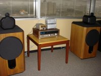
All recently picked up a pair of speakers that are orders of magnitude harder to drive than my 15 ohm 100 dB Lowthers in a TQWT. Knowing the fairly high output impedance of the Rev C, I starteed looking for something more suitable to drive them.
Due to long term vistors at home, I left the speakers in my office. Hooked them up to my lowest power Rev C, Plovati gold stereo board and a single 200 VA ecore power transformer.
Surprisingly, the bass extension is very good. The control is maybe a weakness. Seemed to boom a little. Positioning, and maybe doing the Van Alstine mods to the speaker crossovers may solve this.
Here is a pic of my new office BOOM box.
George
Attachments
- Home
- Amplifiers
- Chip Amps
- My "audiophile" LM3886 approach