Re: Here it is...
I am a bit confused on why you stuck with single sided "compromised" board when you will have the boards manufactured.
Why not optimize the PCB from the get go if you know it will be made by professional PCB makers and offered for sale?
Don't get me wrong, I think the boards look great and hope they come out as well as they look, but I just went through this exact same issue with the Krell KSA-50 klone.
Jan did an excellent single sided board so everyone could etch, then I went and did a GB on manufactured boards..
We sold out of those boards and a "second GB" was started but this time since the agreement going in was for manufactured boards, the layout changed significantly. Same circuit, just RADICALLY different layout that was enabled via the two sided PCB's.
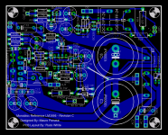
Russ White said:...This is the version of the board I will send to be manufactured...
I am a bit confused on why you stuck with single sided "compromised" board when you will have the boards manufactured.
Why not optimize the PCB from the get go if you know it will be made by professional PCB makers and offered for sale?
Don't get me wrong, I think the boards look great and hope they come out as well as they look, but I just went through this exact same issue with the Krell KSA-50 klone.
Jan did an excellent single sided board so everyone could etch, then I went and did a GB on manufactured boards..
We sold out of those boards and a "second GB" was started but this time since the agreement going in was for manufactured boards, the layout changed significantly. Same circuit, just RADICALLY different layout that was enabled via the two sided PCB's.
I think for two [EDIT: three] reasons.
1) single sided boards are cheaper.
2) redesigning the board means a lot of redesign work, ordering prototypes, building and testing the prototypes to be sure they are as good as the original. A lot of added time and cost.
3) one more reason: the single sided boards are already very small. Why make them smaller? Part density will hardy improve, as there is very little free space now.
BrianDonegan said:I think for two [EDIT: three] reasons.
Hey you beat me. 😉
You are correct on all points. The biggest reason for me for is that I have already prototyped this board, and I am absolutely certain it is solid.
Cheers!
Russ
Which one?
I have a technical question on the Rev A vs Rev C boards. My speakers can be a problem They are 16 ohms rated, 12 - 13 ohm DCR. But they are high inductance. At 15 - 20k Hz the impedance is 30 -40 ohms.
The Rev A seems to handle this rising impedance well. Will the Rev C be as stable? I have read that the C may have stability issues due to the more complex feedback network.
George
Re: Which one?
I can only honestly say I have not tested such a load (I don't have any speakers like that), but I think on REV C if you omit R42 and replace it with a jumper stability should be OK. I used 47ohms there and there is no hint of instability with anything I have tried so far (from 4ohm to 12ohm).
Cheers!
Russ
Panelhead said:I have a technical question on the Rev A vs Rev C boards. My speakers can be a problem They are 16 ohms rated, 12 - 13 ohm DCR. But they are high inductance. At 15 - 20k Hz the impedance is 30 -40 ohms.
The Rev A seems to handle this rising impedance well. Will the Rev C be as stable? I have read that the C may have stability issues due to the more complex feedback network.
George
I can only honestly say I have not tested such a load (I don't have any speakers like that), but I think on REV C if you omit R42 and replace it with a jumper stability should be OK. I used 47ohms there and there is no hint of instability with anything I have tried so far (from 4ohm to 12ohm).
Cheers!
Russ
Russ White said:...The biggest reason for me for is that I have already prototyped this board, and I am absolutely certain it is solid.
Cheers! Russ ...
Russ- No doubts about it being solid and VERY well executed. As a single sided board it is EXCELLENT.
However parts placement is sometimes compromised on single sided boards and double sided opens up huge opportunities to shorten paths, optimize placement, and cut size.
Again, I understand size is not a concern, and the circuit is stable.
I am not in any way, shape or form doubting or knocking the PCB or your work.
I am simply stating that if it was a known fact that the PCB would be professionally manufactured why wasn't it designed (or at least investigated) as a double sided board.
Slight cost increase in production is greatly justified by the path distance gains and parts layout. Again I point to the KSA-50's PCB's as a prime example. AL was able to optimize so much more because he was freed from the one sided restriction.
Increasing the board price 1-2 dollars for double sided, and .5 -1 for a second prototype fee is VERY reasonable for the sonic improvements that "MAY" be gained.
And a final time... The board is great, I never knocked the current product... I simply ask that you consider, before you commit to production, the minor cost of a second prototyping fee as compared to a totally optimized PCB.
Am I missing something? Is the Rev. C a stepping stone to the "D" version? Am I jumping the gun by wanting a "finalized" product that is clearly fore-seeable?
rabstg said:
Russ- No doubts about it being solid and VERY well executed. As a single sided board it is EXCELLENT.
Am I missing something? Is the Rev. C a stepping stone to the "D" version? Am I jumping the gun by wanting a "finalized" product that is clearly fore-seeable?
Thanks for you kind remarks,
One thing to note, it would be very difficult to get the signal traces appreciably shorted even with a double sided board, so there is not a big motivation for doing so.
The revisions are not mine, but Mauro's, so when he is finished is up to him. 🙂 That aside, really each revision could be viewed as a finished product, each being easily good enough to stand alone.
On this circuit there is next to no compromise for using a single sided design. There are only 2 jumpers.
People have been waiting for weeks to get this board, and the most practical and dependable way to get a good product out is to use this tested PCB.
I will work on a double sided board to see if there are any real gains to be had, but for now I think I will go forward with this in the interest of cost, time, and completeness. If I wait until I have a chance to complete and test a 2 layer board it will draw the process out 30-60 days for what I see as very little payoff, which I think is impractical.
I agree with your points, but for practical purposes I don't think I will go dual layer just yet, not for this run. the payoff is just not there that I can see.
As Brian said, the boards are small, thus there really are no "long" traces at all.
Still, your point is taken, and perhaps in future work the two sided board will be my first choice, I just have to build in time to get the prototypes back.
I think your observations do apply more to KSA50 boards than to this one, as the part arrangment there is quite different.
And thanks again for your kind words, and I take your comments with the goodwill I know they were delivered with.
Cheers!
Russ
Two sided board
The main advantage I see is using the back side to replace the jumpers.
Also I see you have a relay on each board. Is this a single pole relay? I like using dual relays and switches even for single pole applications. By paralleling the poles the contact resistance is halved and if one side gets intermittant you never know it.
Plus I found some nice ones locally that fit the Rev A circuit board.
This is not to say dual pole relays are better. This just how I like using them.
George
Circulating Currents
Whew, I'm jumping rather late, but only just finished reading this thread after being pointed to it by a college.
I have a comment on the layout. The take off points for the 318's power supply are part way down the traces from the main caps to the 3886. Since the 3886 is essentially running class B you have the problem that these traces contain half wave rectified components of the output signal. No matter how wide the traces are they have resistance and act as a potential divider. You thus run the risk of picking off energy from this half wave rectified source. The only insulation the 318 has from this appearing on its power pins is the little zener/cap regulator. Certainly general advice from op-amp manufactures is to treat to the power pins as signal input pins (which they are) and to condition the power with as much care as you would the music signal.
The obvious and simple change to the layout is to run a separate parallel trace back to the main P/S caps for each of the resistors that supply the 318 power. You will notice this is essentially treating the power supply rails in the same manner as a star ground for ground return currents - which it is and for exactly the same reasons.
Maybe someone would like to try a quick flying lead modification to see if my concerns actually make a difference.
Re: Circulating Currents
Hi Francis!🙂
Better late than never. 🙂
I actually would go further than that... 😀 I think ultimately an optimized regulation scheme for the 318 would be better. 🙂 Either completely discrete or a 3x7 solution of some sort.
I will try powering the LM318 section with wires directly to the cap pins today and see how it measures. I am taking the amp to UT for some cursory checks (just to be sure it does not oscillate and that THD,SNR are good).
It would be a simple matter to move the 1W resistors a little, and place pads for wires to the big caps. I will see what other options I have.
One should note though, that this amp sounds quite sweet just as it is... so I would suspect if there is any imporvement it may possibly be measurable, but I am not sure it will be audible. 😀
We should also note, I am trying to stay pretty faithful to Mauro's REV A design even to the point of trying to make my PCB layout very much like his REV A layout. That does not mean I am not working on ideas of my own! I have had a few conversations off the list with Carlos Martinez and others, and have taken most of the Rev C circuit and exchanged the shunt regulator for an LM317HV and an LM337 as well as a few other minor changes. Well, I should be able to prototype that version next week, so stay tuned, but that is now no longer a "Mauro Penasa - My Ref" it is a "Russ White - My Ref". 🙂
Cheers!
Russ
Francis_Vaughan said:Whew, I'm jumping rather late, but only just finished reading this thread after being pointed to it by a college.
Maybe someone would like to try a quick flying lead modification to see if my concerns actually make a difference.
Hi Francis!🙂
Better late than never. 🙂
I actually would go further than that... 😀 I think ultimately an optimized regulation scheme for the 318 would be better. 🙂 Either completely discrete or a 3x7 solution of some sort.
I will try powering the LM318 section with wires directly to the cap pins today and see how it measures. I am taking the amp to UT for some cursory checks (just to be sure it does not oscillate and that THD,SNR are good).
It would be a simple matter to move the 1W resistors a little, and place pads for wires to the big caps. I will see what other options I have.
One should note though, that this amp sounds quite sweet just as it is... so I would suspect if there is any imporvement it may possibly be measurable, but I am not sure it will be audible. 😀
We should also note, I am trying to stay pretty faithful to Mauro's REV A design even to the point of trying to make my PCB layout very much like his REV A layout. That does not mean I am not working on ideas of my own!
I have had a few conversations off the list with Carlos Martinez and others, and have taken most of the Rev C circuit and exchanged the shunt regulator for an LM317HV and an LM337 as well as a few other minor changes. Well, I should be able to prototype that version next week, so stay tuned, but that is now no longer a "Mauro Penasa - My Ref" it is a "Russ White - My Ref". 🙂Cheers!
Russ
for your review. 🙂
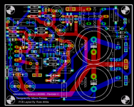
I have made a revision implementing Francis' suggestion and I think it is actually a nice change. Only adds two jumpers on the bottom of the board, and should make the 318s power supply better isolated.
That bring the total jumpers to 4. Not bad at all, less than the original REV A PCBs.
Cheers!
Russ
Attachments
possibly be measurable, but I am not sure it will be audible.
That must almost be a heresy in some quarters 🙂
Something else to think about in the layout, in much the same vein as the previous comment. I like to always think about where the currents are flowing, and look to the return paths, and then reduce loop area. The current layout of the power and grounds is pretty hard to beat on a single sided board, but the amp's output and return are rather ill defined. Even the dressing of the cables might help here - I would be trying to lay the output cable back over the power traces then between the P/S caps and then twisting together with the output ground. Basically trying to keep it close and parallel to the power and ground tracks so that no matter which phase the amp is conducting, the loop area of the power traces, output traces and cables is minimised. Clearly a double sided board would allow for lots more optimisation here, but I won't buy into that discussion 🙂
Regulation of the P/S for the 318 is an interesting issue. I think the crucial thing to remember is that power supply accuracy isn't important, what is important is lack of noise, particularly signal correlated noise. Just another R/C filter may be better. But keeping induced currents from the high power parts of the amp out of the 318 P/S and signal paths will likely be just, if not more, important. Hence why layout is so crucial.
The headphone guys can get pretty full on about regulation of op-amps. The PPA design uses a Jung super-buffer topology (so related to this design) and they go quite overboard with selected capacitors and isolation of the driver op-amps. Might be worth a look. http://elvencraft.com/ppa/
Francis,
So I suppose your criticism(constructive and appreciated as it is) would also apply to Mauro's original PCB? Which BTW, more than a few of us have already built and appreciate very much. 🙂
Please keep in mind I am currently working on a double sided version, but really in the spirit of DIY since I plan on giving this to all to enjoy I like the idea of at least having a solid single sided board to offer.
keeping the layout single sided means that those who will etch this thing themselves will have a much better chance of success. 🙂
Thanks for the good advice I am listening intently. Also please remember that while I fee like I am picking up a lot, PCB design is something I have only been doing for a couple months, and amp building only since January. So, I expect to have lots more to learn.
Thanks to Mauro, and everyone else who has chipped in.
Cheers!
Russ
That it is a clearly successful design does make any perceived criticism an interesting issue (if it isn't broken etc. 🙂 ) I do agree about the single sided board. I tend to feel that intelligent design can usually provide a very good layout without resort to double sided for an amp. Since you have indicated you are working on a clean start design I thought some further thoughts might be interesting. Looking to the current flows and loop areas is always a good idea, and in a class B design crucial.
Of course I have an interest here, because I'll probably want to build a few myself. 🙂 I'm rather impressed with this design.
Of course I have an interest here, because I'll probably want to build a few myself. 🙂 I'm rather impressed with this design.
Four jumpers
I am not very good at reading these, but I only see one jumper, on the grounds. Is there one connected from + and - to pads 2 and 3. Also from O_SP to OUT SP2?
Look forward to building this unit also. It looks very good. Any chance of using the same output relay as the Rev A? I think the added reliability of having paralleled relay contacts is great. There is almost no chance both contacts will become intermittant.
On the voltage regulation for the LM318 the simple scheme used should be fine. The trick is how much voltage is dropped across the 1K resistor. As is, it is 22 volts. No matter how hard the 3886 is run, the rails will not pull down even close, so the 318 should see a steady supply voltage. The inefficiency of this method allows it to perform fine.
Also to address heat generation. Mine gets a little warm after a couple hours playing. The box is almost sealed, it may be the heat boiling off the 1K and 470 ohm resistors. The box has a layer of mumetal glued to the top and bottom for shielding and damping. There is then a rubber layer on top of the mumetal.
Next time it is apart I will add some ventilation to the box. Those 1K resistors are plenty hot.
George
Russ White said:I have made a revision implementing Francis' suggestion and I think it is actually a nice change. Only adds two jumpers on the bottom of the board, and should make the 318s power supply better isolated.
That bring the total jumpers to 4. Not bad at all, less than the original REV A PCBs.
Cheers!
Russ
I am not very good at reading these, but I only see one jumper, on the grounds. Is there one connected from + and - to pads 2 and 3. Also from O_SP to OUT SP2?
Look forward to building this unit also. It looks very good. Any chance of using the same output relay as the Rev A? I think the added reliability of having paralleled relay contacts is great. There is almost no chance both contacts will become intermittant.
On the voltage regulation for the LM318 the simple scheme used should be fine. The trick is how much voltage is dropped across the 1K resistor. As is, it is 22 volts. No matter how hard the 3886 is run, the rails will not pull down even close, so the 318 should see a steady supply voltage. The inefficiency of this method allows it to perform fine.
Also to address heat generation. Mine gets a little warm after a couple hours playing. The box is almost sealed, it may be the heat boiling off the 1K and 470 ohm resistors. The box has a layer of mumetal glued to the top and bottom for shielding and damping. There is then a rubber layer on top of the mumetal.
Next time it is apart I will add some ventilation to the box. Those 1K resistors are plenty hot.
George
Re: First attempt at 2 sided monobloc
Looking great!
Russ White said:Had a little time to work on it, here is what I have so far...
Edit: Had old pic, this one is more recent..
Looking great!
Re: Four jumpers
Hi George,
Thanks for the kind words.
There are wire pads right by the caps and by the resistors. I don't think I will build that version, as in that configuration the amp had higher noise than the original. Not sure why....
As for the relay I think I will keep that part, If I used the dual pole type I will have to make the board larger and I am already at the outer limits. 🙁 Plus, I really like those relays I have used them before and they seem very reliable. They are rated for 10amps, and they are placed so that they would be very easy to replace should you need to (very unlikely). They also are inexpensive, and I have a lot of them. 🙂
Thanks for all the great suggestions!
Russ
Panelhead said:
I am not very good at reading these, but I only see one jumper, on the grounds. Is there one connected from + and - to pads 2 and 3. Also from O_SP to OUT SP2?
Look forward to building this unit also. It looks very good. Any chance of using the same output relay as the Rev A? I think the added reliability of having paralleled relay contacts is great. There is almost no chance both contacts will become intermittant.
George
Hi George,
Thanks for the kind words.
There are wire pads right by the caps and by the resistors. I don't think I will build that version, as in that configuration the amp had higher noise than the original. Not sure why....
As for the relay I think I will keep that part, If I used the dual pole type I will have to make the board larger and I am already at the outer limits. 🙁 Plus, I really like those relays I have used them before and they seem very reliable. They are rated for 10amps, and they are placed so that they would be very easy to replace should you need to (very unlikely). They also are inexpensive, and I have a lot of them. 🙂
Thanks for all the great suggestions!
Russ
More input please 🙂
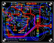
Here is the last revision for the night, I really like the dual sided version, its nice not having the jumpers, but if you guys really want this version you will have to help me double check it as I will not have a chance to prototype it before the GB. That is why I am not deviating too much from the single sided layout. I don't want to muck it up. 🙂
I would like to get this done in the next day or two.
Maybe we should take some sort of vote on what version people want.. Not sure the best way to do that.
Cheers!
Russ
Attachments
Re: More input please 🙂
Well, that's an easy question to answer, we want the best version! 🙂
To find out, shouldn't we have an amp made from each?
What does Mauro think about the 2 sided design?
I guess where we are headed is this 3way decision:
1. Go with a bit of risk on the untested two sided board
2. Go with the proven one sided board
3. Delay the GB while the two sided board gets prototyped and proven.
I guess I'm a 3, but I'm not scratching around for something to do at the moment, 2 amps already in the pipe 🙂 Others may be chomping at the bit for this GB I guess.
Michael
Russ White said:Here is the last revision for the night, I really like the dual sided version, its nice not having the jumpers, but if you guys really want this version you will have to help me double check it as I will not have a chance to prototype it before the GB. That is why I am not deviating too much from the single sided layout. I don't want to muck it up. 🙂
I would like to get this done in the next day or two.
Maybe we should take some sort of vote on what version people want.. Not sure the best way to do that.
Cheers!
Russ
Well, that's an easy question to answer, we want the best version! 🙂
To find out, shouldn't we have an amp made from each?
What does Mauro think about the 2 sided design?
I guess where we are headed is this 3way decision:
1. Go with a bit of risk on the untested two sided board
2. Go with the proven one sided board
3. Delay the GB while the two sided board gets prototyped and proven.
I guess I'm a 3, but I'm not scratching around for something to do at the moment, 2 amps already in the pipe 🙂 Others may be chomping at the bit for this GB I guess.
Michael
- Home
- Amplifiers
- Chip Amps
- My "audiophile" LM3886 approach