Re: More MODS
why not trying?
The unity-gain stability of the OPA549 should definitely be a plus.
Needless to say, this is not just a couple of cascaded stages, like a gainclone with a buffer... you need to re-design everything, and have to know what you're doing.
BTW, since we are talking about possible departures from this design to something new based on it, what I would like to try is a fully discrete design as follows:
It would be worth trying, IMHO.
Sproggit said:Right.
Now just to upset everyone, how would I go about implimenting BB OPA 627 + OPA 549 in this config?
why not trying?
The unity-gain stability of the OPA549 should definitely be a plus.
Needless to say, this is not just a couple of cascaded stages, like a gainclone with a buffer... you need to re-design everything, and have to know what you're doing.
BTW, since we are talking about possible departures from this design to something new based on it, what I would like to try is a fully discrete design as follows:
- a SKA GB150 (or GB300!) configured for fully-balanced (differential...) operation (of course with its default overall NFB loop removed) in place of the LM3886;
- a JFET LTP in place of the LM318 (driving the SKA-based Howland Current Pump differentially).
It would be worth trying, IMHO.
Re: More MODS
There is no reason not to try it, but you will not be able to compensate it in the same way as we do the LM318 for the REVC.
I have made a similar amp with no issues. In fact for the current pump there is no need to use a chip at all. 🙂
Give it a go.
Cheers!
Russ
Sproggit said:Right.
Now just to upset everyone, how would I go about implimenting BB OPA 627 + OPA 549 in this config?
Regards
Jan
There is no reason not to try it, but you will not be able to compensate it in the same way as we do the LM318 for the REVC.
I have made a similar amp with no issues. In fact for the current pump there is no need to use a chip at all. 🙂
Give it a go.
Cheers!
Russ
DAMMIT
Now I had to go look at twisted pair audio.
Russ, you swine, you've made me go all DIY excitable again! 🙂
Have mailed you for twisted OPA 549 Power modules.
And would the be any point in more high end pre-amps for the instrumentation amp on the pre-amp modules (e.g OPA 627?)
Regards
Jan
Now I had to go look at twisted pair audio.
Russ, you swine, you've made me go all DIY excitable again! 🙂
Have mailed you for twisted OPA 549 Power modules.
And would the be any point in more high end pre-amps for the instrumentation amp on the pre-amp modules (e.g OPA 627?)
Regards
Jan
Jan,
While I like the 627 a lot, the LM4562 is actually substantially better than the OPA627 for the application. Also the boards are designed for a dual op amp, and operate with symmetrically loaded rails so its a great fit.
OPA549 modules may come at some point, but I have lots of other projects to finish first.
Cheers!
Russ
Quite unlikely. For safety reasons, I would always opt for a double pole power switch (at least with unpolarized mains outlets like we have here in Germany), I even go for double fuses (one in each branch) sometimes.maxlorenz said:Ah! One idea
I used single path (two pins) power interruptor, instead of double path (four pins) interruptor. Could this be the cause...i.e. instantaneous asymetric power rails or something.
Snubbering a power switch is always a good thing to extend its life. Not across the switch contact (it isn't off for AC then) but from one pole to the other, at both inputs and outputs of the switch (assuming a double pole switch). The RC must have the appropriate approvals for mains use (dont build it, buy an approved intergrated one).I remember I used R-C accross the other amp's power interruptor (to prevent arcing I guess). Is it worth it here?
Regards, Klaus
[OT]Russ White said:While I like the 627 a lot, the LM4562 is actually substantially better than the OPA627 for the application.
Did I mention I hate the NS guys for duplicating the 4562 under the LME49720 label and don't state equivalence in the spec sheets? 😡
Ah, anyone yet went for a monster current pump or other amp design with an Apex PA05 hybrid? Despite its *very* high cost it looks very appealing...
[/OT]
Regards, Klaus
Hi,
One fuse can blow and leave the circuit powered up but apparently dead, until you stick your hand/tools in!
I have one IEC socket (made in Germany) and it has both lines fused. I am considering how to make it safer.
T3.1A in the Live line and T10A in the neutral line? Pondering before I commit.
All my other IECs are single fused.
The equipment MUST have both Live AND Neutral switched.
Similarly, the (wall) socket outlets have both lines switched or neither.
not good practice.I even go for double fuses (one in each branch) sometimes.
One fuse can blow and leave the circuit powered up but apparently dead, until you stick your hand/tools in!
I have one IEC socket (made in Germany) and it has both lines fused. I am considering how to make it safer.
T3.1A in the Live line and T10A in the neutral line? Pondering before I commit.
All my other IECs are single fused.
Double pole switching is mandatory in the UK.For safety reasons, I would always opt for a double pole power switch
The equipment MUST have both Live AND Neutral switched.
Similarly, the (wall) socket outlets have both lines switched or neither.
Dear Brian,
Can you point me to the "relay part" of the schematics? I only have the "amp part".
Thanks,
M
Can you point me to the "relay part" of the schematics? I only have the "amp part".
Thanks,
M
maxlorenz said:Dear Brian,
Can you point me to the "relay part" of the schematics? I only have the "amp part".
Thanks,
M
First post of this thread. 🙂
page 2 of the PDF.
The PS section is the same for all the MyREF revisions from A to C.
First post of this thread.
The PS section is the same for all the MyREF revisions from A to C.
Oh, shame...
Thanks Russ
maxlorenz said:Thanks guys, for the replies.
*I lack the "relay part" of the schematics, though.
http://www.diyaudio.com/forums/attachment.php?s=&postid=609507&stamp=1112280850
mains safety issues
Regards, Klaus
Yep Andrew, therefore I then usually have a "mains present" indicator (LED) installed, right at the power inlet. OTOH, with only one fuse and a partial short from the "wrong" end to earthed chassis/other conductor which draws not enough current for the household breaker to trip, things might catch fire. Had that once and learned from that. Sort of the same problem with a single pole mains switch (those are, though definitely a potential source of hazard, still allowed in Germany).AndrewT said:Hi, not good practice.
One fuse can blow and leave the circuit powered up but apparently dead, until you stick your hand/tools in!
Regards, Klaus
Re: mains safety issues
The fuse MUST be rated for the smallest unprotected conductor down stream.
So the distribution board Fuse/Breaker/MCB protects the household wiring and the socketoutlet/plugtop.
The plugtop fuse protects the flex running to the equipment and the equipment connector.
The equipment fuse protects the internal wiring PRIOR to the secondary side.
One should try to get sufficient discrimination between the fuses to prevent multiple fuses blowing for the same fault.
One could also fit RCCB (earth leakage breaker) to detect a small increase in current flowing to safety earth.
Protection arranged so, should never allow fire to start.
I fit soft start to allow the equipment fuse to be close rated and thus avoid having to fit enormous wiring inside the power amp to match an otherwise over-rated fuse that can be three to five times larger than needed.
this is completely at odds with the purpose of the fuse(s).KSTR said:..........with only one fuse and a partial short from the "wrong" end to earthed chassis/other conductor which draws not enough current for the household breaker to trip, things might catch fire. Had that once and learned from that. ........
The fuse MUST be rated for the smallest unprotected conductor down stream.
So the distribution board Fuse/Breaker/MCB protects the household wiring and the socketoutlet/plugtop.
The plugtop fuse protects the flex running to the equipment and the equipment connector.
The equipment fuse protects the internal wiring PRIOR to the secondary side.
One should try to get sufficient discrimination between the fuses to prevent multiple fuses blowing for the same fault.
One could also fit RCCB (earth leakage breaker) to detect a small increase in current flowing to safety earth.
Protection arranged so, should never allow fire to start.
I fit soft start to allow the equipment fuse to be close rated and thus avoid having to fit enormous wiring inside the power amp to match an otherwise over-rated fuse that can be three to five times larger than needed.
Ah, I probably used unclear wording to explain the scenario, with "wrong side" I didn't mean the secondary:
Fixed power cable ("cold" conductor, by chance) --> switch (SP) --> fuse --> primary -##-> power cable ("hot" conductor). Earthed device (a spare motor controller, not my design) was off but connected (for many years). At the ## segment the isolation deteriorated over time, the wire connected to an only partly grounded heatsink it ran alongside (bad practise aspect here) and the current through the circuitry to PE/GND set the device on fire. The fuse was 250mA AFAIR and would surely have blown long before if there had been two of them in either mains conductor. And a DP switch would have prevented the accident in power off and would have changed the effects to one the fuses blowing on the next power up.
-------:--------
I have those earth leakage breakers (outlet plug-in types) in use and strongly recommend them for any DIYer. They saved my life several times. Even better are medical grade mains isolation transformers. Andew surely agrees...
Regards, Klaus
Hi all,
Earth leakage circuit breakers are compulsory here under the local building code. Fortunately, this was law when we built our house, so we have a full complement of them!
Andrew, you brought up single fused IEC sockets. I have one on my Chipamp kit GC which has on the reverse the three lugs for the inputs from the plug, and two separate, smaller lugs for either terminal of the fuse, which is inserted via a tiny drawer arrangement into the socket so you can't touch the fuse while it's live. So the rear of the socket has three large, and two smaller spade terminals.
How are these designed to be wired? I simply placed the fuse in series with the 'live' but I haven't figured why the fuse isn't simply connected at the time of manufacture. So, the live comes into the plug, there's a short jumper wire to one side of the fuse socket, then from the other side the live continues to the switch then transformer.
I hope you understand what I mean, and do appreciate your attention to safety detail on this forum. FY interest, we don't have fused wall plugs like in the UK (I'm from Scotland but have lived here since I was 4).
Sorry for straying OT. By the way, this is relevant as I've built up some RevC's which are waiting to be put into a chassis once I've built my pre-amp... 😉
Stuey
Hi,
my internal fuse is inline with the Live output terminal.
Some make this connection internally and some are rivetted externally to the Live.
I cannot see why the fuse is wired separately but it allows a more flexible approach to powering controls and other auxiliaries.
my internal fuse is inline with the Live output terminal.
Some make this connection internally and some are rivetted externally to the Live.
I cannot see why the fuse is wired separately but it allows a more flexible approach to powering controls and other auxiliaries.
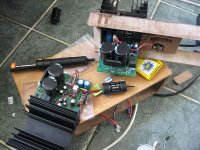
I know I took my own ggod time... but look I just completed putting in the new resistors from TP as well as swapping the 2 front 100nf caps for the 220nfs provided... will leave the rest... desoldering doublesided is too nerve wrecking... I channel done, 1 to go. Forgot I still need to swap in the 10mfd caps too, the ones on the board saw pretty constant high temps for about a year or so, due to my first case being too small and under heatsinked...
Can't wait to power it up... still my favourite chipamp, allthough as you can see mine has had some custom TLC over time.... it allready sounded better than the standard version. Sure its no discrete amp...but it one of the most detailed sounded I have heard.
You guys realy ought to bring these back in production...it saddens me to see people buying those basic kits on the marketplace... when this should be out there...
Attachments
Hi,
I've build up 2 mono blocks of myrevC and now I have a problem:
When powered up, there is Music playing already, when relais clicks after a few seconds, music signal decreases to almost silence. 😕
Same effect vice versa when Amp turned off...
-didnt change any parts
-soldered anything 'fine'
-it's on both channels
-used 2 transformers each one 24v 500VA, wired to 24v 0V 24V (also measured)
Can anyone give me a hint where to look please?
Regards, Micha
I've build up 2 mono blocks of myrevC and now I have a problem:
When powered up, there is Music playing already, when relais clicks after a few seconds, music signal decreases to almost silence. 😕
Same effect vice versa when Amp turned off...
-didnt change any parts
-soldered anything 'fine'
-it's on both channels
-used 2 transformers each one 24v 500VA, wired to 24v 0V 24V (also measured)
An externally hosted image should be here but it was not working when we last tested it.
Can anyone give me a hint where to look please?
Regards, Micha
You can hear music coming through before powering up and after powering down?
A closer pic of the XLR connectors might help to verify they are wired correctly. Has anything else in your signal chain changed?
Your trafos look like they are wired properly. As a confirmation test, if you measure AC between AC1 and AC2 on each board, you should get ~48V.
Also, you might want to shorted your power wires and route them away (as much as possible) from all of your signal leads. You may pick up quite a bit of interference from those EI trafos in the middle of the case.
Have you tested each channel outside of the case, one at a time? This might help point to the problem. Also, verify that your signal + and GND are connected to the correct pins.
- Home
- Amplifiers
- Chip Amps
- My "audiophile" LM3886 approach