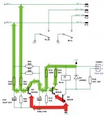
schematic for Rev. C
What page of this endless thread is the Rev. C full schematic on? I've been looking to no avail. Just built up for first Rev. C (already have a Rev. A). I want to make sure I got all the bases covered.
thx,
Tom
What page of this endless thread is the Rev. C full schematic on? I've been looking to no avail. Just built up for first Rev. C (already have a Rev. A). I want to make sure I got all the bases covered.
thx,
Tom
Re: schematic for Rev. C
I think that's here.
tommytube said:What page of this endless thread is the Rev. C full schematic on? I've been looking to no avail. Just built up for first Rev. C (already have a Rev. A). I want to make sure I got all the bases covered.
thx,
Tom
I think that's here.
Protos,
Thats a nice amp man. Very cool having everything integrated in one nice chasis.
I like it! 😀
Cheers!
Russ
Thats a nice amp man. Very cool having everything integrated in one nice chasis.
I like it! 😀
Cheers!
Russ
thanks Russ,
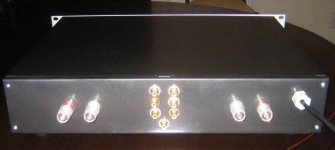
In fact I think the painting of this chassis took up more time than the electronics.The graphite metallic paint would never really dry hard and would mark easily even after a week.Redid it three times!
The best chassis for diyers and an innovative way to allow a modular approach and easy mounting on a professional looking box is ezchassis .Maybe slightly expensive but for that expert finish i think this guy is really providing a solution to many diyers.
Funny thing is he is in New Zealand!
http://www.gumboot.com/cgi-bin/ezshop/shop/2052?category=15&categorygo.x=1
need PS schematic as well
Hi all,
I would like page 2 of the schematic which likely contains the power supply section. Also any layer plots of the silkscreen so I can find stuff easily would be helpful.
Does Twisted Pear have a documents section for this sort of thing?
I want to make sure I'm hooking up power correctly. Where does AGND need to come from? I have two (2x24VAC) power toroids.
thx,
Tom
Re: need PS schematic as well
Hi tom,
The PS is same as Rev A schematic in the first few pages of this thread.
For 2 x 24VAC tarfo you would connect the secondaries in series and the point at which you tie the two secondaries together is your Power GND (0V) which is also what is connected to IN_GND via the 1ohm resistor.
You essentially turn a dual 24V trafo into a 48VCT trafo. 🙂
Cheers!
Russ
tommytube said:Hi all,
I would like page 2 of the schematic which likely contains the power supply section. Also any layer plots of the silkscreen so I can find stuff easily would be helpful.
Does Twisted Pear have a documents section for this sort of thing?
I want to make sure I'm hooking up power correctly. Where does AGND need to come from? I have two (2x24VAC) power toroids.
thx,
Tom
Hi tom,
The PS is same as Rev A schematic in the first few pages of this thread.
For 2 x 24VAC tarfo you would connect the secondaries in series and the point at which you tie the two secondaries together is your Power GND (0V) which is also what is connected to IN_GND via the 1ohm resistor.
You essentially turn a dual 24V trafo into a 48VCT trafo. 🙂
Cheers!
Russ
bpa
if i built a bpa with the lm4780's supposedly giving 230W into 8ohms, does anybody have recomendations on the rating of the speakers i should match to it.😕
if i built a bpa with the lm4780's supposedly giving 230W into 8ohms, does anybody have recomendations on the rating of the speakers i should match to it.😕
After playing around with the amp too much i accidentally connected one of the ac to the power ground.
I replaced both op-amps but i am getting -36 V at amp output -13v at both the inputs of the lm318 and + 11.7 at the output of the lm318.
All power supply voltages are ok and everything else seem to measure ok.
Any ideas?
Thanks.
I replaced both op-amps but i am getting -36 V at amp output -13v at both the inputs of the lm318 and + 11.7 at the output of the lm318.
All power supply voltages are ok and everything else seem to measure ok.
Any ideas?
Thanks.
Check the feedback loop
You may have opened up the feedback loop. Check voltage at C9. Should be plenty if threre is -36 volts on output.
George
You may have opened up the feedback loop. Check voltage at C9. Should be plenty if threre is -36 volts on output.
George
Probably Q3 is dead, maybe all three of the to-92 transistors. They have a leg sitting on GND, and rail voltage, and are tied to the 3886 outputs (DC monitoring). When you put AC on the GND, it prolly killed one or more of these, and they are now conducting rail direct to output. Just a guess.
Attachments
Finally done my REV C
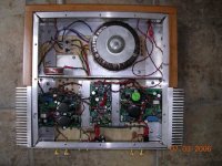
With the generous help of Brian, I finally completed my first electronics project, an intergrated Rev C with a kookaburra as a preamp. In my amp the input cap on the amp and the output buffer on the preamp are bypassed. I found that bypassing the input cap on the amp made an audible difference for the better, bypassing the output buffer also helped but was less obvious.
The build went off without a hitch, I flipped on the power and mucic came out. The amp is smooth, warm, clear, and detailed. After burning it in for a week I auditioned it against a Denon, and a vintage Marantz 1060. The Denon sounds hard, bright, and flat, compared to both the Marantz and the RevC, tough to listen to for long periods. The RevC is a lot like the Marantz in tonality, both are smooth, and on the warm side, but the Marantz has less detail, clarity, and sounds more rounded off around the edges. Rev C seems to have better base control too, still the 1060 does sound nice. The RevC is very addictive sounding, after listening to it for a while it's hard to be satisfied listening to other amps. Kudos to Russ and Brian for a really great quality kit. Bravo to Maurio for an excellent design.
Attachments

Re: Finally done my REV C
Can't argue with that. 🙂
Very good job mate. Thats a nice looking project, and I think you made some good decisions on the build.
Enjoy it! 😀
Cheers!
Russ
Nortp said:The RevC is very addictive sounding, after listening to it for a while it's hard to be satisfied listening to other amps.
Can't argue with that. 🙂
Very good job mate. Thats a nice looking project, and I think you made some good decisions on the build.
Enjoy it! 😀
Cheers!
Russ
Very Nice amp 🙂
Dear Russ and Brian, now I got money and time to go for my RevC monoblocks but it says "Temporarily out of stock" on your site 🙁 When will they be available?
I will try My-ref with my DIY "technical balanced power" unit this weekend, I hope. It always makes a significant difference for the better 😉
http://www.equitech.com/articles/articles.html
Best regards
M
Very soon. 🙂
It is a crazy time for me at work right now, and I am also moving. So I don't have much free time right now. 🙁
It is a crazy time for me at work right now, and I am also moving.
So I don't have much free time right now. 🙁Thanks 🙂
I know you are busy: I found by chance "the other" threads. Very nice projects, Twisted X Overture and Twisted Sibling.
I hope you will be attracted to active biamping some day because I need a good sounding active crossover. 😀
Good luck and happy life in your new house 🙂
M
I know you are busy: I found by chance "the other" threads. Very nice projects, Twisted X Overture and Twisted Sibling.
I hope you will be attracted to active biamping some day because I need a good sounding active crossover. 😀
Good luck and happy life in your new house 🙂
M
BrianDonegan said:Probably Q3 is dead, maybe all three of the to-92 transistors. They have a leg sitting on GND, and rail voltage, and are tied to the 3886 outputs (DC monitoring). When you put AC on the GND, it prolly killed one or more of these, and they are now conducting rail direct to output. Just a guess.
Thanks Russ,
I thought of something like that too.I took out q1 q2 and they measure well hfe etc.Q3 seems to be measuring ok on the board at least with the mm diode checker- so not shorted of couse.The voltages i am getting are with q1q2 removed.
So I think it is something else.
George mentioned the feedback loop .I have measured the cap there and it is ok so i will check the voltage while on.It would be strange though if a feedback resistor opened or even a track on the board don't you think?However looking at the schematic since i measured -13v at the -input(3) of the lm 318 then there should be -13v on the positive side of c9 as well since they are connected.So I am still confused...
- Home
- Amplifiers
- Chip Amps
- My "audiophile" LM3886 approach