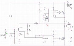
I built this amp based on a N-channel quasi I did a very years ago, and then married it to the JLH front end.
Sonically it is very nice, and handles capacitive loads at ease (notice the 2uf cap on the output terminal), because of the current feedback.
You can also run the traditional differential front end but need to use a higher miller cap (C8). I have fond that the design is quite insensitive to the choice of transistors and if you adjust R13, R14, and R15, you can also use bipolars as well.
Attachments

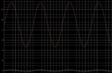
Very good stability into a capacitive load.
Despite using dual rails, why is C3 (3300uF) required at the output?
Despite using dual rails, why is C3 (3300uF) required at the output?
Hi tlf9999,
why not bias your input base from ground directly and run a variable resistor from the =ve supply to the feedback C at the emitter and adjust for DC offset. A little simpler.
samuel Jayaraj,
You're right - there's no need for the output C of3M3F, but I'll be damned if I can see how you evaluate stability on 20KHz sine - and in the dark as well! My hat's off to you.
but I'll be damned if I can see how you evaluate stability on 20KHz sine (posted by amplifierguru)
I understand that it should have been a square wave test but there are too many amplifiers that will begin to oscillate even when passively connected to such a large reactive load, let alone being tested dynamically. Isn't the 'normal' output inductor there only to combat such capacitive loads? And how many of these (commercial) amps can safely be terminated with high capacitance cables, more so without the output inductor?
I understand that it should have been a square wave test but there are too many amplifiers that will begin to oscillate even when passively connected to such a large reactive load, let alone being tested dynamically. Isn't the 'normal' output inductor there only to combat such capacitive loads? And how many of these (commercial) amps can safely be terminated with high capacitance cables, more so without the output inductor?
Samuel Jayaraj said:Despite using dual rails, why is C3 (3300uF) required at the output?
because the simulation was done with 0vdc negative rail.
I wouldn't run this on +/- rails without a DC servo. The DC offset does wonder more than if differential pairs are used on the front: about 30-40mv, similar to pretty much all current feedback amps I have used.
Although Output Offset Voltage close to zero volts is desirable, upto 100mV should not normally be a problem. Remove the output cap and please report back.
I also ran a version on NPN output devices (mjl21193 ?), with minor changes (driver resistors) to the original circuitry.
- Status
- Not open for further replies.
- Home
- Amplifiers
- Solid State
- my amp