Some time ago I posted the overall results of my amp, starting here: http://www.diyaudio.com/forums/solid-state/240712-cfa-topology-audio-amplifiers-483.html#post3839020 Some 0.006% THD20 @ 800W/2ohm, with 8 pairs of MJL Onsemi bipolars, not too shabby.
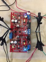
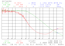
The driver SMD PCB got another revision and, because I've never seen (other than in simulation) a two pole compensated amplifier, I measured the loop gain of this ultra linear driver board. I could go up to 3MHz ULGF with the improvised output stage (effectively halving the distortions to 0.003% THD20), but it would mean pushing my luck, so I kept it at a decent 1.2MHz. Attached is the loop gain/phase and a photo of the new board.
Simulated ULGF is 1.4MHz (1.2MHz measured) and the simulated phase margin is 75 degrees (measured 67 degrees). Pretty good match, actually unexpectedly good for DIY, given the quality of the available models.
Took a few nights of work, but worth showing what a great level of audio futility can be accomplished with modern devices. Yes, at normal listening levels it sounds exactly as good (or bad) as my salvaged HK amplifier. 800W into 2ohm is obviously only "because we can".
Attachments
The driver SMD PCB got another revision and, because I've never seen (other than in simulation) a two pole compensated amplifier, I measured the loop gain of this ultra linear driver board. I could go up to 3MHz ULGF with the improvised output stage (effectively halving the distortions to 0.003% THD20), but it would mean pushing my luck, so I kept it at a decent 1.2MHz. Attached is the loop gain/phase and a photo of the new board.
Simulated ULGF is 1.4MHz (1.2MHz measured) and the simulated phase margin is 75 degrees (measured 67 degrees). Pretty good match, actually unexpectedly good for DIY, given the quality of the available models.
Took a few nights of work, but worth showing what a great level of audio futility can be accomplished with modern devices. Yes, at normal listening levels it sounds exactly as good (or bad) as my salvaged HK amplifier. 800W into 2ohm is obviously only "because we can".
Waly you are fanny when you say two pole compensated amp never seen actually built, only simulated. You can find just enough example of a built two pole compensation amps in this forum.
And show the schematic, don't play fanny games with us.
And show the schematic, don't play fanny games with us.
Seems to be top-secret rocket science...
Best regards!
Waly you are fanny when you say two pole compensated amp never seen actually built, only simulated. You can find just enough example of a built two pole compensation amps in this forum.
And show the schematic, don't play fanny games with us.
I said, I've never seen a two pole compensated amp loop gain/phase measurement. Have you?
It may look "fanny", but I can't disclose the schematic, it is a rocket science commercial product. I'm not going to miss this opportunity to abandon designing mixed signal ICs and get stinkin' rich
 .
.I said, I've never seen a two pole compensated amp loop gain/phase measurement. Have you?
It may look "fanny", but I can't disclose the schematic, it is a rocket science commercial product. I'm not going to miss this opportunity to abandon designing mixed signal ICs and get stinkin' rich
OK, but this is DIY forum, at least explain how do you measure two pole compensated amp loop gain/phase.
OK, but this is DIY forum, at least explain how do you measure two pole compensated amp loop gain/phase.
That's easy, voltage injection, I used a self made 10:1 wideband transformer (on a small ferrite toroid AL=10,000, it's good up to about 5MHz), a 4195A network analyzer and a pair of 41800A FET input 1:1 active probes. All clear now?
Last edited:
That's easy, voltage injection, I used a self made 10:1 wideband transformer (on a small ferrite toroid AL=10,000, it's good up to about 5MHz), a 4195A network analyzer and a pair of 41800A FET input 1:1 active probes. All clear now?
You know what, I don't like your patronizing ton.
You know what, I don't like your patronizing ton.
I know 😛, truth is not necessary convenient. There's a cute option called ignore list, what about using it?
I know 😛, truth is not necessary convenient. There's a cute option called ignore list, what about using it?
I don't use ignore list and do not have intention to start to use it because of you. You just like to show your superiority, listing some tools not available to most of DIY community. If you want to help here you have to change your behavior, but I've lost the hope.
Really nice workmanship with the PCB and soldering of all the SMDs, even if I don't understand anything about the circuit.
...Attached is the loop gain/phase and a photo of the new board....
Board looks nice, done how? hot air reflow, IR, hand iron, other?
...I used a self made 10:1 wideband transformer (on a small ferrite toroid AL=10,000...a 4195A network analyzer and a pair of 41800A FET input 1:1 active probes...
Didn't you work on a Rosenstarck style injection system a while back?
Did that turn out?
Best wishes
David
Circuit? Which circuit?
A circuit with no less than 58 transistors. Why bother posting the schematic, only for hearing a loud "It's way too complex to sound good"? "The signal goes through too many nonlinear devices", "Too much GNFB to sound good", etc... OTOH, I have no plans for a finished amp, since my resources to invest in case, heatsink, power transformers, big electrolytics, hardware and machining facilities are non existent. I can't find more than a couple of M3 screws in the lab.
Good luck building Blameless variants, it's indeed the shortest path to a very good amplifier. My purpose was only to show how close can the simulations and measurements results get. Within 10% is very good, given the poor device models we have.
Exercise for the reader: why is the loop gain measurement limited at some 70-80dB at LF? Simulation shows over 160dB. Hint: is an instrumentation limitation.

Thats true. All my blameless designs are working like a charm....
Good luck building Blameless variants, it's indeed the shortest path to a very good amplifier.
...
Congratulations that you got your design running even with so many devices!
IMHO it's good to know, that there is another verified piece of amplifier hardware which measures in real life very close to ltspice simulations using free available transistor models.
As most of us do not have a 4195A network analyzer and a pair of 41800A FET probes maybe this simple breadboard method helps others to check gain/phase margin:
I reduce compensations caps until the oscillations starts - compared to the simulations it was always pretty close to my ltspice simulated designs...
BR, Toni
P.S.: I and many others are still interested in the circuit!
Your statement
only for hearing a loud "It's way too complex to sound good"? "The signal goes through too many nonlinear devices", "Too much GNFB to sound good" ...
is only partially true. Of course in every forum you will find people criticizing a special circuit topology. But all others are willing to learn...
This is indeed a useful exercise. Shame we can't expand the data set beyond one.
Although, for me, I'm going to build in a 10% safety margin on stability margins in future.
Although, for me, I'm going to build in a 10% safety margin on stability margins in future.
58 transistors? That's not bad. My current diamond-output jfet input amp design is a mere 28 (56 for two channels). Or are you cheating and using diode-connected transistors?
I see you're using a lot of duals. Do you have preferences? I've got a reel of IMX8 and IMT4 duals which I quite like - 120V, 50mA, Hfe ~400, fT 300MHz at 10mA... Also they're in a SOT26, which is easy-peasy to solder with a 0.95mm pin pitch.
I'd like to use dual 2n3904s, but thus far all I've found is much smaller packages.
Exercise for the reader: why is the loop gain measurement limited at some 70-80dB at LF? Simulation shows over 160dB. Hint: is an instrumentation limitation.
I think I know this one even without the hint!
V source injection doesn't handle non-idealities of injection point.
That's why I asked about Rosenstarck injection immediately prior to your post😉
Looked like you did some work on that, so what did happen to it?
Best wishes
David
58 transistors? That's not bad. My current diamond-output jfet input amp design is a mere 28 (56 for two channels). Or are you cheating and using diode-connected transistors?
I see you're using a lot of duals. Do you have preferences? I've got a reel of IMX8 and IMT4 duals which I quite like - 120V, 50mA, Hfe ~400, fT 300MHz at 10mA... Also they're in a SOT26, which is easy-peasy to solder with a 0.95mm pin pitch.
I'd like to use dual 2n3904s, but thus far all I've found is much smaller packages.
I also use IMT, IMX and IMZ. And FMMB5401/5551, also in SOT23-6.
I think I know this one even without the hint!
V source injection doesn't handle non-idealities of injection point.
Wrong guess. The root cause is called "dynamic range". When you measure directly a ratio with 16bit A/D converters, the maximum ratio is theoretically 96dB. Noise and other factors are limiting the dynamic range to some 80 dB.
There are ways to increase the dynamic range, but they are beyond of what I have available here.
- Status
- Not open for further replies.
- Home
- Amplifiers
- Solid State
- My amp revisited