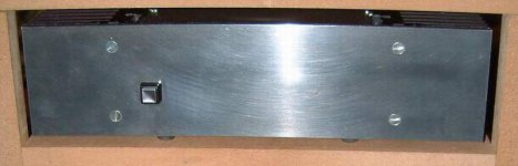
This is my DIY amp. 2*100 w (in 8 ohms load). It's a Zenquito amplifier, the schematic, which can be find
here:http://perso.wanadoo.fr/jm.plantefeve/sche.html
is rellay simple and provides to this amplifier a really good sound.
The sound is really amazing, for only 300$, it's the best amp I never heard.
And now, some pics:
here:http://perso.wanadoo.fr/jm.plantefeve/sche.html
is rellay simple and provides to this amplifier a really good sound.
The sound is really amazing, for only 300$, it's the best amp I never heard.
And now, some pics:
Attachments
Hi SDF,
Great job!
You'r really good!
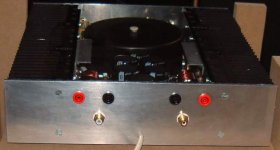
I'v seen also on the last pic. that you have a Meridian underneath your amp. Does it run hot? If so, you better put the amp on a separate shelf!
Ones again very nice! congrats!
Audiofanatic 😉
Great job!
You'r really good!
I'v seen also on the last pic. that you have a Meridian underneath your amp. Does it run hot? If so, you better put the amp on a separate shelf!
Ones again very nice! congrats!
Audiofanatic 😉
Lovey construction, SDF!
Did you make those PCBs yourself? Also, what is the VA rating of that transformer?
See ya,
Tim.
Did you make those PCBs yourself? Also, what is the VA rating of that transformer?
See ya,
Tim.

Its quite nice looking. If you could translate a few more details please.
At 100 watts I assume its AB configuration.
Those chokes on the outputs are wonderful, how did you calculate and fabricate them?
Congratulations.
What advice would you have for any of us who might want to follow in your footsteps?
A translation by google:
http://translate.google.com/transla...ntefeve/sche.html&hl=en&lr=&ie=UTF-8&oe=UTF-8
First thank all 🙂
Audiofanatic :
Concerning the Meridian CD player under this amp, it's not a problem, it's hot but the heat go up so the cd player stay cold.
More It stand on another shelf.
trwh:
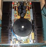
The power rating is 500VA, it's an encapsulated toroid by Nuvotem-Talema. In the target to grow down the wires,I designed my own PCB
Da5id4Vz:
If Ishould give an advice concerning this construction, you should not used a 2*35Vac transformer but 2*30Vac or even 2*25Vac because it's really enough.
This amp is of course a class ab amplifier which biased about 110 mA by device so 232 mA by chanel (second stage required 10 mA and the first 2mA).
The output shoke is approximatively 1 µH, 10 rounds of 20 mm radius give it.
Audiofanatic :
Concerning the Meridian CD player under this amp, it's not a problem, it's hot but the heat go up so the cd player stay cold.
More It stand on another shelf.
trwh:
The power rating is 500VA, it's an encapsulated toroid by Nuvotem-Talema. In the target to grow down the wires,I designed my own PCB
Da5id4Vz:
If Ishould give an advice concerning this construction, you should not used a 2*35Vac transformer but 2*30Vac or even 2*25Vac because it's really enough.
This amp is of course a class ab amplifier which biased about 110 mA by device so 232 mA by chanel (second stage required 10 mA and the first 2mA).
The output shoke is approximatively 1 µH, 10 rounds of 20 mm radius give it.
Thank seangoesbonk
For the interesting people, my speaker associate with this amp is here :
http://www.diyaudio.com/forums/showthread.php?s=&postid=154375#post154375
For the interesting people, my speaker associate with this amp is here :
http://www.diyaudio.com/forums/showthread.php?s=&postid=154375#post154375
Nice to see that someone has built the Zenquito and like it. I have
been tempted to try that amp myself for some time. Although
one cannot judge sound quality from a schematic I like the
simple straightforwardness of the design.
I do have a few questions for you, if you don't mind:
Do you use the transistors suggested by the schematic? When
searching the web for sources of the input JFETs, they seem
to be very hard to find and are listed as obsolete.
Which MOS-FETs and how many, do you use? The suggestions
given on the website seems way too conservative. The Hitachi
devices can dissipate 100W each so there seems hardly any
reason to doubling them even for the 80W amp even if
running in class A. Using double BUZ905DP seems extreme
overkill.
It's real easy to make those chokes, just take something round and wind! The value isn't very critical. 0,5-2 µH is a normal value. 15-25 turns, diam 10-15 mm. Wire diam 1-2 mm.Da5id4Vz said:Those chokes on the outputs are wonderful, how did you calculate and fabricate them?
I hate AWG


Nice amp BTW.
Christer,
I use two pairs of Hitachi transistor (per chanel), the couple 2SK1058 and 2sj162, but with my (too) high voltage I must use them in class AB. The first stage transistors are JFET 2SJ103 2SK246, there are available in France, but anywhere else, I don't know.
About sound, even if I don't know your taste, I'm sure you will be enjoyed. Sound really accurate and powerfull seriously and to compare with commercial product I won't exchange my amp by a Krell KAV300i.
I give you an advice to do one with a 2*30Vac transformer and you will listen lot, lot, lot of music
comparing with crescendo, more details and the smooth of medium treble is better too. Do it and you will compare yourself
SDF,
have you measured the idle current of the amp? Although i don't
really speak french, I understand most of the text about the amp,
so I see that it should have 1.5A idle current in class A. however,
I cannot find any info on the idle current in class AB. If I don't
misunderstand, the bias resistors should be 68 Ohms for class AB
and 150 Ohms for class A, so the idle current would be rather
high also for class AB. I have done some Spice simulations today,
but I used different transistors in the VAS, since I don't have
any models for the ones in the schematic. Hence, I may get
values which are quite off from what they should be.
Hello Christer,
The idle current in my amp is 235 mA, the first stage is about 2 mA, the second made with 2NXXXX, is about 10 mA, and the final stage should be biased at 110 mA by device (I use two pairs), so the Idle current in class AB, is 2+10+110+110=232 mA,
Approximately 235 mA.
Concerning the bias resistor, you said true 😉
Hm, that's interesting. If you have 2mA in the input stage, and
10mA in the VAS, the Vbe of the VAS would be 2V. That seems
unreasonable for any BJT.
Anyway, It was foremost the OPS bias I was interested in and
110mA seems a reasonable value. Is that the value you
happened to get or have you found some info specifying that
it should be 110mA? The design is somewhat unusual in that
the OPS bias is set indirectly by adjusting the current in the
input stage. As far as I understand, the text says the input
stage current should be 1mA, rather than 2mA as you have.
Did I misunderstand that or otherwise is there a reason you
set it to a higher value?
I never mesure how current flow in the first and second stage, 2 and 10 mA was given to have an 'order of idea'.
The 110 mA I choose, give the thermal indefference, same stand off point for 25 and 50°C.
For have a good bias (near the linearity of class A), the typical curves Id=f(Vgs) give 150 mA bias by device.
So I try with this bias and the result was not really different (I don't listen, I mean same sound ), so I decide to get down until 110 mA in the target to reduce the dissipate power.
I didn't take over the two first stage, I juste set in gross the current which flows in output device. 110mA for me
Make this amp and bias it with 150 mA or 110mA, in this two cases you won't be disappointed....
- Status
- Not open for further replies.
- Home
- Amplifiers
- Solid State
- My amp is completed !