I would like comments on this design.
The driver and output transistors are sustained beta types which I think are better than the MJE 340, 350 - 2955, 3055. Outputs are Sanken devices roughly like the Toshiba A1302 C3281 but rated at 17A.
Will this thing even fly?
1. I am not an EE, just a hobbyist.
2. Don't know Spice, wish I did.
The driver and output transistors are sustained beta types which I think are better than the MJE 340, 350 - 2955, 3055. Outputs are Sanken devices roughly like the Toshiba A1302 C3281 but rated at 17A.
Will this thing even fly?
1. I am not an EE, just a hobbyist.
2. Don't know Spice, wish I did.
Attachments
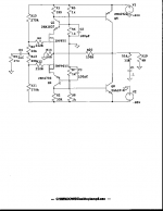
![amp8[1].gif](/community/data/attachments/10/10972-9e82d2b10f00dfbb548c8117bf90d774.jpg?hash=noLSsQ8A37)
You have a potential problem here: high output impedance. Collector out gives you 1-10 kohm. You should have << 1 ohm output impedance in order to drive speaker without colouring the sound. I sucpect that your open-loop gain is too low. You can't feedback away the high impedance.
You must find a trick to reduce the output impedance (before you feedback the signal).
You must find a trick to reduce the output impedance (before you feedback the signal).
Thanks
Thanks for the input and help.
Perhaps I have not biased the stages high enough to give a good open loop gain. I wanted 20ma. at the input and 100 ma. for the output stage. This may be too low as I don't know what pspice uses for the threshold voltage of the fets. Maybe tweaking R3, R13 up from 20k would increase the bias of both stages and the OL gain? Say 100ma. for the input and .5 A at the output. R1, R2 may need to be tweaked to get the right bias. I also thought that the NTC of the input fets would aid the thermal stability if mounted on the heatsink.
dshortt9,
100 mA idle current for the output devices : your amp works in class AB. I think you will have problems with thermal stability, and therefore severe crossover distortion, depending on actual power output, voltage supply variations... Also, open loop gain seems to be very low.
Regards, P.Lacombe.
100 mA idle current for the output devices : your amp works in class AB. I think you will have problems with thermal stability, and therefore severe crossover distortion, depending on actual power output, voltage supply variations... Also, open loop gain seems to be very low.
Regards, P.Lacombe.
OK, After some more thought let's change R1, R2 to 6.6 ohms to bias the front end at 100ma and the output devices at 500ma. R3, R13 will also need to be tweaked to accomplish this. With these conditions I have an OL voltage gain of about 400 and a sensitivity of .1 V at 100W into an 8 ohm load. This only allows me about 20 db of feedback for a 1 V sensitivity, not enough to correct output impedance and distortion. Remembering what Mr. Pass said in his ZEN articles I don't think I can get more than a voltage gain of 10 regardless of what fets I would use in the front end so I'm stuck. Sure is hard to get something for nothing! Obviously I could add a driver stage but my mindset is to accomplish the goal with 2 stages. More mental excersize than reality at this point.
Thanks to all
Thanks to all
Would bipolars be a better choice for the input devices so there would be a log/antilog = linear type thing happening from the first device input to the second device output?
GP.
GP.
Good Thought, There is more voltage gain ~ 1000 and the linearity is improved a lot. If we would then bias the outputs at 1 A both stages are very linear and we will have 40db of feedback for low distortion, but Im afraid the output impedance may still be higher than acceptable. Can anyone calculate or approximate this? Am I wrong in thinking that an output transistor running at 60 V and 1 A has about 60 ohms of resistance ( roughly = impedance ) and that 40 db would lower this to 0.6 ohm. I'm not technically proficient enough to know if this is close.
You must check once again the output stage (or the lack of it).
How many amps have purely collector out? Noone! Why? You can't get low output impedance at audio frequencies. If you wanted a bass amp you could have extremely high open-loop gain but that's no way to go for fullrange audio.
I suggest that you test your design with small signal transistrors and a aupply voltage of +-12-15 V, then you (maybe) will belive me ( I could be wrong but I don't think so). You can make some things better with higher bias currents but that's only aspirin for a brain tumour (right spelled?, I meen cancer).
peranders said:You have a potential problem here: high output impedance. Collector out gives you 1-10 kohm. You should have << 1 ohm output impedance in order to drive speaker without colouring the sound. I sucpect that your open-loop gain is too low. You can't feedback away the high impedance.
You must find a trick to reduce the output impedance (before you feedback the signal).
I could very easy find myself design an amp a bit this way if it is stable... As Nelson says, the feedback forms the outputimpedance.
Sonny
my amp design
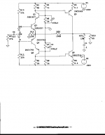
Another thing to be carefull about is the standing current in the output stage. This topology will be very hard (impossible) to stably bias. It is very very difficult to tweak the resistor values for say 100mA in the output stage in a physical implemenation, whatever Spice will say. Look away for 10 secs and it may go down to 10mA, or, more likely, to 10 A. At the very least, put a small resistor in Q5 and Q8 emitters.
Cheers, Jan Didden
I can't tell you what the output impedance is but think of it this way - the output transistors are arranged basically as current sources which by definition have infinite output impedance. You know how on the characteristic curves for a transistor for a given base current you wind up the collector voltage and plot the graph? The graph of collector current goes up pretty steep initially and then goes almost horizontally across the page, uphill ever so slowly even though the collector voltage gets higher and higher. That is the "resistance" of the transistor, a *change* of 50 volts might make a *change* of collector current from 1 amp to 1.01 amps so it is 50/0.01 = 5000 ohms! I think this is called slope resistance. So you got high output impedance, man.
GP.
GP.
Okay you guys do not get it!
Without feedback it will have a high output impedance, but with feedback it is another story!
It is basicly a RR output like the ones designed in a RR output opamp. And they can have a outputimpedance as low as milliohms because of the feedback.
I think you should go read some books about feedback and opampdesign. Sorry if i am rude! But i mean it.
Sonny
Here is a link to an amp that uses a collector output:
http://www.gmweb.btinternet.co.uk/mf-a1.htm
Also, follow this link and look at section 4.4 - Complementary Sziklai Output Stage.
http://www.ee.und.ac.za/Courses/dne4ec1/PwrAmpNotes.htm#_Toc515065899
What I'm attempting to do is refine this stage to be a complete amp if possible.
Look at section 8 of this document for an amp using this output configuration.
Another familiar implementation:
http://w1.521.telia.com/~u52107110/tr_monster.html
Here is one using a mosfet output, but i think a bjt could be used with some changes.
http://home.zonnet.nl/tschrama/owndesign.html
You could add a emitter resistor to the output devices. Not only could this help getting a stable idlecurrent, but also be usefull for a currentlimiter.
But still you would need some way to get control of the idlecurrent. Design a circuit with bias a extra current to the bases on the output devices depending on the temp. of the heatsink!?
Sonny
But still you would need some way to get control of the idlecurrent. Design a circuit with bias a extra current to the bases on the output devices depending on the temp. of the heatsink!?
Sonny
sonnya said:Okay you guys do not get it!
Without feedback it will have a high output impedance, but with feedback it is another story!
It is basicly a RR output like the ones designed in a RR output opamp. And they can have a outputimpedance as low as milliohms because of the feedback.
Sonny
If you have feedback of 60 dB (rather much!), it means that you reduce the output impedance with a factor of 1000. Let's say the transistors output impedance is 10 kohm (I don't know the real value, maybe down to 1 kohms iat higher currents) this gives 10 to 1 ohm out. 1 ohm may work but will colouring the sound especially if the speaker is "difficult". 10 ohms out is a total catastrophy! You lose 3/4 of the output power for starters, it's only 6 dB but it surely will colouring the sound.
A friend of mine built a Hiraga amp (class A) with collectors out and with moderate feedback. The amp didn't sound good with my friend's speaker (with difficult charateristics).
Listen to the old boys, use emitters out. "Grundtips" (basic tips) as we say in swedish.
Where did you find power BJT with a VA of more than 1000V? I would like to know.
More realistic : VA = 200 + half supply voltage = 250V.
ro ~= va/ic => 250Ohm
Two BJT(NPN+PNP) ro = ro/2 = 125Ohm.
Openloop gain of 1000times.
125mOhm.
By the way : Monster is more like a inverted compound (emitter follower?)
Sonny
More realistic : VA = 200 + half supply voltage = 250V.
ro ~= va/ic => 250Ohm
Two BJT(NPN+PNP) ro = ro/2 = 125Ohm.
Openloop gain of 1000times.
125mOhm.
By the way : Monster is more like a inverted compound (emitter follower?)
Sonny
sonnya said:
Openloop gain of 1000times.
125mOhm.
What do you mean?
Openloop gain of at 1000. How much feedback do you suggest?
Wanted gain must be 20-30 dB. 60 dB feedback gives 80-100 dB open-loop gain. Anybody will no fix that. Oscillations or a slow amp.
- Status
- Not open for further replies.
- Home
- Amplifiers
- Solid State
- My Amp Design