It’s hard to work out with no scale (to lazy to attempt scaling it); some of the “tracks” look a bit close together. For example look under the four pin header pin 3, V+ and V- look very very close but it could just be due to the image being a picture format online.
As you have coped so well with my pedantic-ness so far let me make another wild suggestion, Being limited in board size for the main Amp board have you considered going SMT ? you would as far as I know be the first DIY Aleph X in SMT.
As you have coped so well with my pedantic-ness so far let me make another wild suggestion, Being limited in board size for the main Amp board have you considered going SMT ? you would as far as I know be the first DIY Aleph X in SMT.
Hi all,
Well, I knew that board already, and it looks really great. There are a couple of things about it which do not convince me completely, though:
1. The heatsinks overlap the top layer. As was pointed out previously in this thread, the solder mask cannot be relied upon as insulator.
2. The board cannot easily accommodate both the TO-220 and the TO-247 package, and I wanted this kind of flexibility.
As I said, that board looks great, though, nice and compact.
Actually I believe you're right concerning the insulation distance between V+ and V-, I will correct it.
As for the SMT, well... it' s just me, but I really hate them when it comes to solder them!
Cheers,
Bruno
steenoe said:Hi Bruno, here is a rectifierboard that's known to work🙂 Just for inspiration😉 http://www.diyaudio.com/forums/showthread.php?s=&threadid=42105&highlight=
Your A-X boards are looking great😎
Steen🙂
Well, I knew that board already, and it looks really great. There are a couple of things about it which do not convince me completely, though:
1. The heatsinks overlap the top layer. As was pointed out previously in this thread, the solder mask cannot be relied upon as insulator.
2. The board cannot easily accommodate both the TO-220 and the TO-247 package, and I wanted this kind of flexibility.
As I said, that board looks great, though, nice and compact.
mark stones said:It’s hard to work out with no scale (to lazy to attempt scaling it); some of the “tracks” look a bit close together. For example look under the four pin header pin 3, V+ and V- look very very close but it could just be due to the image being a picture format online.
As you have coped so well with my pedantic-ness so far let me make another wild suggestion, Being limited in board size for the main Amp board have you considered going SMT ? you would as far as I know be the first DIY Aleph X in SMT.
Actually I believe you're right concerning the insulation distance between V+ and V-, I will correct it.
As for the SMT, well... it' s just me, but I really hate them when it comes to solder them!
Cheers,
Bruno
Carondimonio said:As for the SMT, well... it' s just me, but I really hate them when it comes to solder them!
Cheers,
Bruno
Send me four boards and I would send you two back soldered up

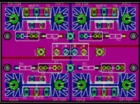
Rectifier board Version 2
Hi all,
I redesigned the rectifier board and made it more compact (3.1" x 2.2"). What do you ¨think?
😀 Would you get the boards if they aren' t SMT?😀
Cheers,
Bruno
Hi all,
I redesigned the rectifier board and made it more compact (3.1" x 2.2"). What do you ¨think?
mark stones said:
Send me four boards and I would send you two back soldered up
😀 Would you get the boards if they aren' t SMT?😀
Cheers,
Bruno
Attachments
Designer Devil,
just today my girlfriend offered to buy me a pair of 275 Euro special magnafying glasses she was offered in some medical journal.
For my electronic fiddlings.
No, not-smt is fine by me.
rectifier board looks fine.
just today my girlfriend offered to buy me a pair of 275 Euro special magnafying glasses she was offered in some medical journal.
For my electronic fiddlings.
No, not-smt is fine by me.
rectifier board looks fine.
Yep, that thing looks great😀Would you get the boards if they aren' t SMT?
Steen😎
Hi Steen ,
thats right , i had that in Mind !
Sorry off topic , but would you share a little bit about the little wonder ?
i mean the little pre on the other tread ?
Jürgen
thats right , i had that in Mind !
Sorry off topic , but would you share a little bit about the little wonder ?
i mean the little pre on the other tread ?
Jürgen
Sure, Jurgen, but could you please post your question in the NS10 thread? Just so it is easy to do a search😉 I can tell you , the "little wonder" as I doped it, really is great, even with average components!😉 You can safely build one for yourself😉Sorry off topic , but would you share a little bit about the little wonder ?
Steen😎
Re: Rectifier board Version 2

Its much better, the tracks around the heatsinks could be a bit thin you could fill them (under the heatsink)and then use an insulator between the heat sink and the diode(I know this goes against what I said before but you had multiple traces under them on the other board). So even with insulators it was possible to short tracks.Carondimonio said:Hi all,
I redesigned the rectifier board and made it more compact (3.1" x 2.2"). What do you ¨think?
Yes I would if you make then available, I threw in the smt suggestion because I like reading the replies that quickly follow when you use this abbreviation, it may not be long before it gets listed as a swear word and banned from the forum. Ha (sorry guys and girls)Carondimonio said:😀 Would you get the boards if they aren' t SMT?😀

Re: Re: Rectifier board Version 2
Hi all,
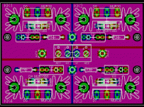
well, I' ve looked into the datasheets and found out that this heatsink can come already fitted with teflon insulators, which raise it apprx. 1.5 - 2 mm above the PCB, so... here' s the new version of the regulator PCB.
Cheers,
Bruno
Hi all,
mark stones said:
Its much better, the tracks around the heatsinks could be a bit thin you could fill them (under the heatsink)and then use an insulator between the heat sink and the diode(I know this goes against what I said before but you had multiple traces under them on the other board). So even with insulators it was possible to short tracks.
well, I' ve looked into the datasheets and found out that this heatsink can come already fitted with teflon insulators, which raise it apprx. 1.5 - 2 mm above the PCB, so... here' s the new version of the regulator PCB.
Cheers,
Bruno
Attachments
Carondimonio said:So... any suggestions more?
Cheers,
Bruno
Sell me some boards.😀
Member
Joined 2002
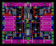
Some minor changes...
Hi all!
well, it' s nice to see such a positive response! Thank you all, guys!🙂 🙂 🙂
Ok, I made a couple of minor changes:
added two additional input pins (-INDC and +INDC), in case the input caps are not installed.
I also changed the heatsink package and used the insulated one (like on the rectifier PCB), to thicken the supply lines.
Attachments
Member
Joined 2002
Carondimonio said:On the rectifier PCB, I added pads for 1N400X diodes. They won' t be used for an AlephX, but can be used for other projects (for example, an ONO... hint, hint... 😀 ):
Cheers,
Bruno
If you are planning to have the ident printed on the boards cut it back around the solder lands.
- Status
- Not open for further replies.
- Home
- Amplifiers
- Pass Labs
- My Aleph-X compact PCB


