Chokes in an Aleph "Mini"
Dear mattworld:
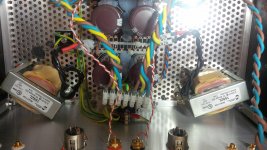
For my Aleph "Mini" build, I did use chokes from Hammond, ZL159:
(sorry, the upload somehow always puts my picture the wrong way up, even if I pre-rotate it ... 😕)

These are 2.5 mH @ 10 A DC chokes, 44 mOhms. At lower currents, Hammond states that they have "higher inductance".
My PSU is CC-L-C with 2 x 33 mF, then the choke, then another 33 mF.
I run about 19 V rails.
The current draw is actually much higher than in your simulation, 4.4 A per rail (2.2 A per MosFET 😎), but the amp is totally silent even with my ear very close to 100 dB sensitivity speakers.
I can highly recommend the CLC configuration. 😉
Regards,
Claas
Dear mattworld:
For my Aleph "Mini" build, I did use chokes from Hammond, ZL159:
(sorry, the upload somehow always puts my picture the wrong way up, even if I pre-rotate it ... 😕)
These are 2.5 mH @ 10 A DC chokes, 44 mOhms. At lower currents, Hammond states that they have "higher inductance".
My PSU is CC-L-C with 2 x 33 mF, then the choke, then another 33 mF.
I run about 19 V rails.
The current draw is actually much higher than in your simulation, 4.4 A per rail (2.2 A per MosFET 😎), but the amp is totally silent even with my ear very close to 100 dB sensitivity speakers.
I can highly recommend the CLC configuration. 😉
Regards,
Claas
Attachments
it would be even better with C-L-CC
Dear Zen Mod:
I had been thinking about putting more capacitance after the chokes after reading various posts here ...
By then, I already had bought BrianGT boards and PSU pcbs (chipamp.com) that came in the CC-L-C. The reason for paralleling the first capacitor according to them is better ability to withstand the ripple currents.
My own simulation with PSUD2 showed that for my planned current of 4 - 4.5 A per rail the "standard" good-quality snap-in caps I found at Mouser in 33 mF capacitance would actually be taxed too much by ripple current, so paralleling the first capacitor made sense in that regard.
I had been thinking of the PSU as C-L-C with a little ripple current relief for the first cap 😀
And after I had assembled the PSU, I did find no need to put more capacitance after the chokes ... 😎
Though I have added some 4.7 µF WIMA MKP10 at the output (they're under the board).
I have much less than 1 mV remaining ripple at the amp outputs - I estimated around 0.3 mV; it's difficult for me to measure these low voltages exactly.
I did change to outboard rectifier bridges from the standard configuration on the PSU board that used 4 diodes for both rails in kind of a "center-tapped" configuration, but that's another story ...
So actually, my reasoning in this post was coming purely from the ripple side, which may be looking too narrowly... just curious, would you see other benefits in C-L-CC ? Maybe sound quality, or peak current delivery ?
Then I need to try it after all ... 🙂
Regards,
Claas
are sure 🙄
sims , in your case show's 0,014 V , in "real world" it could be 0.007 V , not really 0,001 V , but if you say so , that will be so .
to get 0.001 V or even lower , it cost you more than 2,5 mH , lot more , let say x10 more , especially at 4.5 Amps load
But I am here to learn, so why not 😉
capacitance after the choke is the place where the Amp take the load , in your case 4.5 A , so C-L-CC is a good choice 😉
in the end you will do what ever you like , dont you 😀
are your caps rated 25 v or 35 v ?
.
Last edited:
Dear fabrice63:
Sorry, I probably haven't been writing very clear. You're right, at the PSU output remaining 100 Hz ripple would be in the 14 mV range.
The estimated 0.3 mV are at the speaker outputs of the whole amp ... 🙂
I have United Chemicon KMH capacitors with 33 mF and rated for 35 V, so that I could use the PSU with another transformer at the more standard Pass DIY voltages of 23-25 V as well 😉
Regards, Claas
- Status
- Not open for further replies.