Hi and Merry Christmas 🙂,
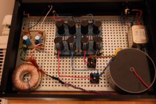
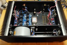
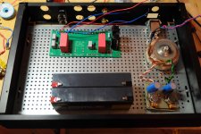
Here you can see my actual configuration for the Aleph J. It is not optimal but it is the way a go for now.
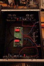
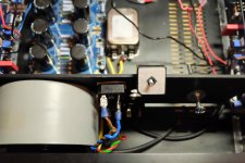
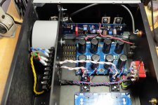
The amp and pre-amp power supply is in the first box. The second case contain the Pass B1 pre-amp board and the 2 Aleph J power supply card.
I am waiting for the V-fet supplemental kit, and I am thinking to reuse the B1 pre-amp.
So in the futur I will use the first case as the pre-amp case with it power supply, the pre-amp card and I will add two 12V batteries I have. I will add a switch to change from charging the batteries to power the preamp.
In the second box I will transfer all the Aleph J power supply (transformer + power supply card).
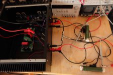
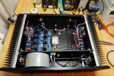
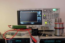
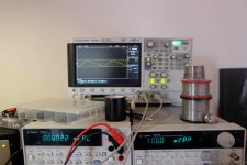
I have take this opportunity to make measurement on the amp. You can see the configuration in the third picture.
Comments are welcome 😉 What would you improve ? I am thinking to add a second power supply to make a dual mono. And perhaps a CLC filter (you will see the problem in the measurement pictures...)
Here you can see my actual configuration for the Aleph J. It is not optimal but it is the way a go for now.
The amp and pre-amp power supply is in the first box. The second case contain the Pass B1 pre-amp board and the 2 Aleph J power supply card.
I am waiting for the V-fet supplemental kit, and I am thinking to reuse the B1 pre-amp.
So in the futur I will use the first case as the pre-amp case with it power supply, the pre-amp card and I will add two 12V batteries I have. I will add a switch to change from charging the batteries to power the preamp.
In the second box I will transfer all the Aleph J power supply (transformer + power supply card).
I have take this opportunity to make measurement on the amp. You can see the configuration in the third picture.
Comments are welcome 😉 What would you improve ? I am thinking to add a second power supply to make a dual mono. And perhaps a CLC filter (you will see the problem in the measurement pictures...)
Attachments
Last edited:
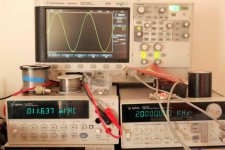
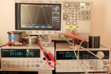
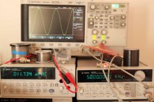
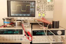
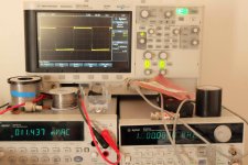
Here is the measurement with a sine signal at 50 Hz, 500 Hz, 5 Khz, 10 KHz, 20 KHz.
The load are two 5.6 ohm power resistors.
The two channels are well paired. I do not see the any problems here.
The load are two 5.6 ohm power resistors.
The two channels are well paired. I do not see the any problems here.
Attachments
Last edited:
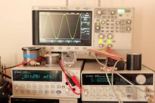
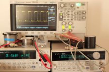
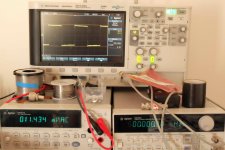
Here are the mesurements with a square signal at : 500 Hz, 1 KHz, 5 KHz, 10 KHz, 20 KHz.
The response is not perfect but seems normal for this type of amplification.
What do you think ?
The response is not perfect but seems normal for this type of amplification.
What do you think ?
Attachments
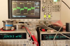
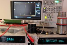
Here is my actual problem. And I think it can be improve.
With no input signal I have 100 Hz hum on both +24V and -24V. It is at about 100 mV or 200 mV peak-peak. Perhaps a CLC filter could improve this ?
The second problem is that my power supply source (the +/- 24V) is clearly modulated by the amplified signal .
Do you have the same problem, is that normal ? Do a bigger / dual power supply could improve the situation ?
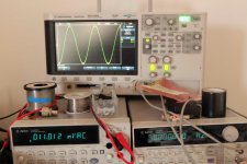
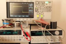
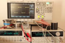
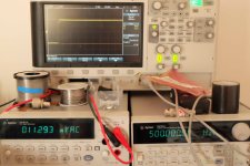
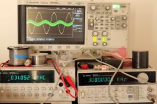
Here is the -24V measurement with a sine and square input signal.
In yellow it is the output signal on the 5.6 ohm load and in green it is the -24V power supply.
Thanks
With no input signal I have 100 Hz hum on both +24V and -24V. It is at about 100 mV or 200 mV peak-peak. Perhaps a CLC filter could improve this ?
The second problem is that my power supply source (the +/- 24V) is clearly modulated by the amplified signal .
Do you have the same problem, is that normal ? Do a bigger / dual power supply could improve the situation ?
Here is the -24V measurement with a sine and square input signal.
In yellow it is the output signal on the 5.6 ohm load and in green it is the -24V power supply.
Thanks
Attachments
Last edited:
It's interesting to see all the different ways that DIYers build the Alleph J. I just finished mine and it is fan cooled with the 2 amplifier boards and heatsinks in one half of a single large chassis, with the power supply occupying the other half.
One issue that can occur with 2 chassis builds is getting the chassis ground and signal ground done right so that you don't get hum. My Aleph J is running balanced inputs and I have the chassis ground near the input connectors and pin 1 of the XLRs goes directly to the chassis. There is absolutely no hum even with my ear next to 95db/w speakers. You could perhaps give a description of how you have wired the chassis ground, power supply ground and input ground. You must have a basic mistake somewhere in order to get such a large amount of hum.
The square wave response looks a bit off to me. You are getting ringing on top of the square wave that should not be there. I remember there being some optional resistors in the circuit to help prevent this sort of thing. If you haven't put them in then that would be a good starting point.
As far as the power supply modulation, that is an indication of the impedance of the power supply. In a dual chassis setup you have a cable running betwen the chassis which will add series resistance to the power supply. This could possibly also add to stability problems. Again, if you give a description of the interconnection method, length of cable, wire gauge etc. it may give some clues as to what is going on.
Hi Bfpca,
Thanks for your answer ! Yes, I think you are right, all this problem can be link to the double chassis and impedance / ground return problem.
Now I remember, when I build the amp, I had to isolate the ground from the earth chassis connection. I had audible hum when my ground was at the earth potential, so it is currently isolated.
I have no varistor from ground to earth chassis like in NP schematic. And ground return is from one big gauge cable (35 cm cable long)
Actually I have no audible hum on the speakers, it is just on the scope. When you make measurement on your power supply you have a clean +/-24V ?
I thought the square response was correct but I should make a try in one chassis ?
1) Please mount your transformers correctly with the supplied mounting kit.
The way you have mounted it with wire, you may have created a shorted turn.
2) Did you deviate away from the official Aleph J schematic? What components are you using in the feedback loop?
3) Did you match the jfets used in the differential input stage
4) Is the CCS that supplies current to the jfets operating correctly
5) Temporarily take out the B1 power supply and send signal directly to the Aleph J amp.
6) I don't see any rectifiers used on your B1 supply
Last edited:
1) Please mount your transformers correctly with the supplied mounting kit.
The way you have mounted it with wire, you may have created a shorted turn.
2) Did you deviate away from the official Aleph J schematic? What components are you using in the feedback loop?
3) Did you match the jfets used in the differential input stage
4) Is the CCS that supplies current to the jfets operating correctly
5) Temporarily take out the B1 power supply and send signal directly to the Aleph J amp.
6) I don't see any rectifiers used on your B1 supply
Hi picoDumbs,
Thanks for the hints,
1) Yes, I will mount the transformer correctly when I'll put it in the case. They were no mounting kit when I bought the transformer.
2) No I do not deviate from the original schematic
3) Yes, I bought the Jfet matched but you think it is not OK ?
4) Can you explain me what is the CCS ?
5) Yes I will do more measurements without the B1
6) The rectifiers for the preamp are the small black components. 😉
One more thing I just remembered.
I seem to recall the B1 PCB is electrically grounded to the chassis via the stand offs of the B1 pcb.
To prevent myself from having a brain aneurism, I think it would be best to put the B1 in a separate case until you've isolated the problem.
1) How is the black wire connected to the psu? What is connected to it at the amp end?
2) Do you have the chassis in both cases connected to earth.
1) Get rid of wire looped around transformer.Hi picoDumbs,
Thanks for the hints,
1) Yes, I will mount the transformer correctly when I'll put it in the case. They were no mounting kit when I bought the transformer.
2) No I do not deviate from the original schematic
3) Yes, I bought the Jfet matched but you think it is not OK ?
4) Can you explain me what is the CCS ?
5) Yes I will do more measurements without the B1
6) The rectifiers for the preamp are the small black components. 😉
3) Depends who you bought them from?
4) From the positive power rail, the differential Jfet input is fed by a constant current source (CCS). This improves the psrr, if it is not functioning correctly you may experience greater power supply ripple on the output.
Could you provide a schematic of your B1 power supply. It looks like you have a symmetric dual polarity power supply. B1 is designed to operate on a single ended power supply.
Try twisting the input signal wires. Or change them to coax. Can't hurt.
Also, you seem to have 2 wires attached to the green pcb in the middle picture of the first post that don't go anywhere. That can't help.
I'm assuming your mains are at 50Hz. Try turning the lights off, especially if fluorescent. Again, don't know if it'll help, but can't hurt.
That's my 2cents, which may be worth a lot less than that.
Hi Bfpca,
Thanks for your answer ! Yes, I think you are right, all this problem can be link to the double chassis and impedance / ground return problem.
Now I remember, when I build the amp, I had to isolate the ground from the earth chassis connection. I had audible hum when my ground was at the earth potential, so it is currently isolated.
I have no varistor from ground to earth chassis like in NP schematic. And ground return is from one big gauge cable (35 cm cable long)
Actually I have no audible hum on the speakers, it is just on the scope. When you make measurement on your power supply you have a clean +/-24V ?
I thought the square response was correct but I should make a try in one chassis ?
I thought you had 100mv of hum at the speaker terminals. Sorry about that. That amount of hum on the +/-24v is probably in the normal range for that type of supply. I have a CLC supply in my J and the 120hz level is much lower, in the 10mv range.
I'll let others comment on the square wave response but it looks a bit odd to me. Have you installed the jumpers at the inputs to the Jfets or did you substitute the 221ohm resistors as indicated in note 3 of the BOM document. Installing the 221ohm resistors may be necessary to improve stability. I put them in on my build.
I thought you had 100mv of hum at the speaker terminals. Sorry about that.
Me too, but does he just mean it's not audible, only measurable on the speaker terminals.
If it's just power supply ripply that is completely different story.
Regarding the oscillating square wave, double the size of the capacitor across the feedback loop, then report back.
One other thing. I don't see a ground wire from the power supply board running out the cable going to the enclosure with the boards in it. There is supposed to be one from that point to each of the boards as well as that point going thru a CL60 to the power cord ground.
Hi,
Thanks you all for the tips about the amp.
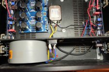
I start to make the modifications. I move the power amp power supply to the first case. It take me a lot of time to cut and mount a plate for the transformer.
The cable length will be a lot shorter 😉
In the same time I prepare the case for the dual mono power supply. The second transformer is on the way home.
The main AC come from bottom, go to the filter and then to the transformer. The diode bridge is mount next to the transformer and will go through the hole to the RC filtre board.
Is the placement good ? What do you think ?
I will make another hole to wire the earth to the case next to the power socket.
Do I need to wire the ground to the case too ? If yes, where should I do it ? With the varistor like in Nelson Pass schematic ? Thanks 😎
Thanks you all for the tips about the amp.
I start to make the modifications. I move the power amp power supply to the first case. It take me a lot of time to cut and mount a plate for the transformer.
The cable length will be a lot shorter 😉
In the same time I prepare the case for the dual mono power supply. The second transformer is on the way home.
The main AC come from bottom, go to the filter and then to the transformer. The diode bridge is mount next to the transformer and will go through the hole to the RC filtre board.
Is the placement good ? What do you think ?
I will make another hole to wire the earth to the case next to the power socket.
Do I need to wire the ground to the case too ? If yes, where should I do it ? With the varistor like in Nelson Pass schematic ? Thanks 😎
Attachments
Last edited:
Me too, but does he just mean it's not audible, only measurable on the speaker terminals.
If it's just power supply ripply that is completely different story.
There were not audible hum on the speakers. The 100/200 mV ripple was on the +/- 24V RC filtre board output (with no input signal).
Also, The +/- 24V output voltage were modulated by the amplified signal.
I have to add two fuses sockets and the varistors to the amp.
I will mesure all again (output voltage / speaker output signal) when amp will be working again. 🙂
Last edited:
I have doubts about the diode bridges. Do I isolate the bottom of the AC bridge with the chassis ?
I have also made the preamp case holes. It will be powered by two 12V batterie. I added a switch and I will replace input cable with coax cable.
I am thinking about adding a relay volume control board. What do you think ? Do you have a good reference ? Thanks !
I have also made the preamp case holes. It will be powered by two 12V batterie. I added a switch and I will replace input cable with coax cable.
I am thinking about adding a relay volume control board. What do you think ? Do you have a good reference ? Thanks !
Attachments
Last edited:
Hi,
I just make some avancement on the amp. The mechanical cut is done. It will be a dual mono aleph J with two transformers. I re wire one of the channels.
Before I was using it with a separate power supply and I had ripple on the amp output and on the +/- 24V power supply (pictures on the previous page).
I made the wires as short as possible and the measurements are a lot better. I don't have any ripple on the amp response now. I have done measurement with the scope at 600Hz, 1 Khz and 20 Khz and it is clean. 🙂 🙂
The amp was load with a 5,6 ohm power resistor and feed by a generator on high impedance mode.
On the power supply I still have a 100mV ripple from the 50Hz.
What do you think of this ripple, is there a way to reduce it ?
The amp is clipping at 30V peak to peak, I think it is ok.
I placed two CL-60. One in series with the primary of the transformer and a second between my ground on the main earth. The first on is ok but the second one smoke when I power up the amp. So it is remove for now... Do you have an idea of the problem here ?
If you have suggestions on the amp wiring or how to improve it don't hesitate. 😉
Attachments


- Status
- Not open for further replies.
- Home
- Amplifiers
- Pass Labs
- My Aleph J actual/futur configuration and mesurements