So for my first DIY project i chose the easy-going, thermally always stable, first-timer recommended F5 Turbo V2 with cascode. Just to add a little bit of challenge, it’s dual mono 
Truth be told: I inherited the project. One other person has failed, another rebuilt the PSU and gave it up due to time constraints and complexity, as well as rumours of the circuits realibilty issues.
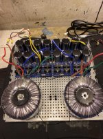
So I am setting up a workshop in my garage. This picture shows the baseplate with inherited PSU boards, and 600va 2x24v 240v transformers. I have not done anything on my oen as of yet, other than planning.
Extensive planning! Most questions are allready answered for now, and I have arrived at the following conclusions to safeguard stability as much as I can:
1: I will use all capacitors, also the optional ones on the output boards.
2: I will increase gatestopper resistance to 220 ohms.
3: I will order alternative higher values for resistors pertaining to bias adjustment: 2k, 3k and 3,3k
4: Cascode and adjusted voltage to 16 volts through the JFETs, using the original Toshiba bipolars. And heatsink them.
5: Possibly increase wattage of source resistors to 5w.
Chassis is a 5U from the store. I have ordered new thermal pads from the store, as well as new FE and output boards. The old, apparently failed, boards, will serve as practice remedies to get my soldering skills up to speed.
I still have unanswered questions, and I really hope for your guidance and assistance. You are an amazing community.
A special thanks goes out to 6L6 for motivating and guiding me to the point where I feel I can do this, for his burning engagement for the hobby and fellow DIYers, and for the gift I received by airmail the other day.
Truth be told: I inherited the project. One other person has failed, another rebuilt the PSU and gave it up due to time constraints and complexity, as well as rumours of the circuits realibilty issues.
So I am setting up a workshop in my garage. This picture shows the baseplate with inherited PSU boards, and 600va 2x24v 240v transformers. I have not done anything on my oen as of yet, other than planning.
Extensive planning! Most questions are allready answered for now, and I have arrived at the following conclusions to safeguard stability as much as I can:
1: I will use all capacitors, also the optional ones on the output boards.
2: I will increase gatestopper resistance to 220 ohms.
3: I will order alternative higher values for resistors pertaining to bias adjustment: 2k, 3k and 3,3k
4: Cascode and adjusted voltage to 16 volts through the JFETs, using the original Toshiba bipolars. And heatsink them.
5: Possibly increase wattage of source resistors to 5w.
Chassis is a 5U from the store. I have ordered new thermal pads from the store, as well as new FE and output boards. The old, apparently failed, boards, will serve as practice remedies to get my soldering skills up to speed.
I still have unanswered questions, and I really hope for your guidance and assistance. You are an amazing community.
A special thanks goes out to 6L6 for motivating and guiding me to the point where I feel I can do this, for his burning engagement for the hobby and fellow DIYers, and for the gift I received by airmail the other day.
Attachments

Thanks! An honor, Mr. pass.
I trust the absence of well mesnt comments on the project, means the plan is with the limits of sensibility.
The gift i mentioned, are the boards for BA-3, complimentary. If F5T fails, I’ll do the BA-3 right away. If not, it will be my next project.
I trust the absence of well mesnt comments on the project, means the plan is with the limits of sensibility.
The gift i mentioned, are the boards for BA-3, complimentary. If F5T fails, I’ll do the BA-3 right away. If not, it will be my next project.
Question 1: I need a good and stable solution to mount boards to the DIY baseplate. The holes are 4mm, which makes a stable fit for normalt standoffs difficult. I have also considered nylon clip on standoffs, but am sceptical about the reability and rigidity of such a solution.
I have also seen people use nylon washers about 1/2 an inch tall. This could work, but ideally I think the bolt should be a snug fit for the washer.
As of now the boards are secured with long bolts, and standoffs are mere nuts. This is atable enough, but a pain in the *** to dismount. And it does not look the part. But it sort of works.
Could not find a good answer to this question searching the forum.
So my question is this: What solution do you guys prefer, and why? Mouser/digikey links or names would be helpful.
Question 2: What remedy do you use to secure the output board thermistors to the heatsink/transistor washer? Just thermal paste?
Question 3: Any gain (or loss) in increasibg restor wattage from 3 to 5 watts, for example the feedback resistors?
Question 3: Any gain (or loss) in increasibg restor wattage from 3 to 5 watts, for example the feedback resistors?
If the hole is large enough that the standoff slips in, you might consider a thin metal washer under the standoff.
Depending on the situation I use either metal standoffs with threaded sections, or big nylon through standoffs.
The thermistor can be placed snug on the mosfet, but take care while doing this. The case of the thermistor may be inconsistent and any small imperfections will cause the output stage to self-destruct. A small thermal pad between the thermistor and the mosfet, or a layer of thermal tape that provides both conduction and insulation, is appropriate.
You can freely increase the resistor wattage. Non-inductive resistors will generally perform better. Resistors that run cooler generate less self noise, not by much though.
Thanks so much, valuable reply for my project.
Wrt the thermistors, I derive that thermal stability is key. Could you take a look at 6L6s solution in the illustrsted build guide? Looks like he used some form of thermal glue. I have bought the same size washers to put on top of the MOSFETs, so I am thinking if doing the same as him wrt the thermistors.
What do you think of that soultion? I see Nelson Pass in the original F5, seems to have put the thermistor against the drain pin.
Of all my attempts at ensuring steady progress of the bias with stable offset, the heatsink has been the most reliable. It has a high enough latency to ensure the offset is relatively stable, at the same time not so high as to result in poor compensation.
I must add that I do not use the documented thermistor method on a regular basis. I choose to use the older compensation outlined in the original F5, which controls overall Vgs. I did once try the official circuit, but with one thermistor on each device (so 4 in total). For this I chose the drain pin and it worked well enough. Latency was very low, though there was quite a bit of jumping in the offset even with well-matched devices. It seems matching thermistors isn't as straightforward.
I just wedge up the thermistor against the heatsink, with one edge butted up against the plastic package of one device. Using a single sensor to control multiple paralleled devices is always a bit tricky, and generally mosfets are significantly less sensitive to small variations in bias compared to bipolar transistors, so fine-grained control is desirable but not critical. If this was a discussion about Vbe multipliers in bipolar output amps, things would be radically different.
It's also been a very long time since I built one of these amps, so my information may be heavily out of date. I switched to lateral mosfets years ago, with appropriate changes to suit the lower OLG.
I am on attempt 2 of the F5 T v2, and still can't wrap my brain around when or why to cascode. Does anyone have a way to explain cascoding to a simpleton? Sorry for the old thread resurrection.
Wes
Wes
So for my first DIY project i chose the easy-going, thermally always stable, first-timer recommended F5 Turbo V2 with cascode. Just to add a little bit of challenge, it’s dual mono
Truth be told: I inherited the project. One other person has failed, another rebuilt the PSU and gave it up due to time constraints and complexity, as well as rumours of the circuits realibilty issues.
So I am setting up a workshop in my garage. This picture shows the baseplate with inherited PSU boards, and 600va 2x24v 240v transformers. I have not done anything on my oen as of yet, other than planning.
Extensive planning! Most questions are allready answered for now, and I have arrived at the following conclusions to safeguard stability as much as I can:
1: I will use all capacitors, also the optional ones on the output boards.
2: I will increase gatestopper resistance to 220 ohms.
3: I will order alternative higher values for resistors pertaining to bias adjustment: 2k, 3k and 3,3k
4: Cascode and adjusted voltage to 16 volts through the JFETs, using the original Toshiba bipolars. And heatsink them.
5: Possibly increase wattage of source resistors to 5w.
Chassis is a 5U from the store. I have ordered new thermal pads from the store, as well as new FE and output boards. The old, apparently failed, boards, will serve as practice remedies to get my soldering skills up to speed.
I still have unanswered questions, and I really hope for your guidance and assistance. You are an amazing community.
A special thanks goes out to 6L6 for motivating and guiding me to the point where I feel I can do this, for his burning engagement for the hobby and fellow DIYers, and for the gift I received by airmail the other day.
It's an umbrella that keeps the fragile jfets dry and safe.explain cascoding to a simpleton
Oh, an umbrella! So I rig some unistrut at 90 deg with some 1/2" c-clamps to keep the rain out? Got it!
below amplifier a 3 x 3 (meters, feet, cubic yards) hole in the earth must be excavated. Fill with concrete of your choosing. Prior to concrete cure, jam a 6 (meter, cm, inch) section of Unistrut into concrete. Eyeball it perpendicular to your perceived horizon. Once lava is solidified, incert
Insert 1/2 (decimeter, cm, inch) c clamps. This is where you determine the level of flair you desire. Golf umbrella? Patio umbrella ? Whatever you feel at the moment.
there is the security umbrella as I understand it
there is the security umbrella as I understand it
The JFETs break down at high voltages. For the Toshiba J74 and K170, the breakdown point is 40 volts. And so, if you run at specified 32 volt rails, there is not much headroom. So it is recommended to cascode at voltages above 30, though Papa ran his original F5T at 32 volt rails without cascodes.I am on attempt 2 of the F5 T v2, and still can't wrap my brain around when or why to cascode. Does anyone have a way to explain cascoding to a simpleton? Sorry for the old thread resurrection.
Wes
A cascode basically reduces the voltage that the JFETs see/are exposed to, making it possible to run high voltage rails to the output stage for more power, without destroying or reducing the life span of the precious JFETs.
But why is this your 2nd attempt? The F5T is perhaps the most difficult and volatile of the First Watt builds. If this is your first amp, or you are not an experienced builder, I would rather go for a BA-3, or an F4.

Thanks, that was a good high level explanation. I appreciate it. 2nd attempt is a result of life getting in the way of continuity.The JFETs break down at high voltages. For the Toshiba J74 and K170, the breakdown point is 40 volts. And so, if you run at specified 32 volt rails, there is not much headroom. So it is recommended to cascode at voltages above 30, though Papa ran his original F5T at 32 volt rails without cascodes.
A cascode basically reduces the voltage that the JFETs see/are exposed to, making it possible to run high voltage rails to the output stage for more power, without destroying or reducing the life span of the precious JFETs.
But why is this your 2nd attempt? The F5T is perhaps the most difficult and volatile of the First Watt builds. If this is your first amp, or you are not an experienced builder, I would rather go for a BA-3, or an F4.
There's also the dissipation issue. You'll notice that the internal ambient of the amplifier can be about 45-50C, at which temperature the allowable dissipation in the JFET is around 240mW as against the 25C rating of 400mW (general guideline for TO-92 devices). In order to offer maximum reliability, it is wise to restrict the part/s to a maximum of about 1/2 the allowable dissipation. A cascode allows you to run current through the JFET close to its Idss value, while maintaining a lower overall dissipation.
Another effect is something I don't see mentioned a lot is that the JFETs enter low noise mode when the Vds is below 12V. A combination of higher Idss (say 8mA) and a low Vds (I target around 10V most of the time) allows you to get a good balance of performance with no downsides.
Another effect is something I don't see mentioned a lot is that the JFETs enter low noise mode when the Vds is below 12V. A combination of higher Idss (say 8mA) and a low Vds (I target around 10V most of the time) allows you to get a good balance of performance with no downsides.
This is helpful - thanks for sharing!…
Another effect is something I don't see mentioned a lot is that the JFETs enter low noise mode when the Vds is below 12V. A combination of higher Idss (say 8mA) and a low Vds (I target around 10V most of the time) allows you to get a good balance of performance with no downsides.
- Home
- Amplifiers
- Pass Labs
- My accidental F5 Turbo V2 w/cascode project