yeah... those heatsinks seem best... 80mm fan per heatsink... fans mounted on the FRONT of a rack mount case... might even get clear fans with coloured LEDs... 😉 could be interesting...
but a case... could be expensive.... I really don't wanna attempt my own... and I don't want raw aluminium.... seems like Jaycar has the best quality ones.... $109 for a 3 Unit case... hmmm but then I have the problem of cutting a CIRCLE the the 3mm thick aluminium front.... and I'm not sure if the heatsinks will fit in the case... need to go in there sometime and see if I can measure one.. 😀 but $109... thats the most expensive part out of everything....
SO FAR!!!
Filter Capacitors: 16 4700uF 100v chasis mount = FREE
Transformers: 3 X 18v CT 250VA = $75
Heatsinks: MF18-151.5 (0.11 C/W with fan) = $80 total
Fans: 2 X 80mm clear LED or plain black = $35-$45 total
Case: Jaycar 3 Unit rack mount case: $109
thats like $190 so far without the case....
$299 with the case.. 🙂
theres a few more components I need... bridge rectifier... some smaller value capacitors... probably a power switch and speaker and RCA sockets... looking at less than $400 total.. 🙂
Just found a PCb from on the web... could be interesting..
http://hepso.dna.fi/misc/lm4780/lm4780-pcb.pdf
greetz,
Thijs
http://hepso.dna.fi/misc/lm4780/lm4780-pcb.pdf
greetz,
Thijs
I never got excited about it either. Try Easytrax (simpler) or Autotrax. (Both DOS). They used to be commercial products by Protel (now Altium) before being put out to pasture as freeware.tschrama said:I just spend a hour or so trying to learn the 'Eagle' PCB layout program... but I am not impressed ..
http://www.protel.com.au/resources/downloads/index.html bottom of page.
Don't make PCBs. Use two rows of "machined contact" type IC socket on solderable perf board, and then run flying leads from there. It's far more rugged and adaptable than a circuit board. I put the big stuff on a tag strip.
Cheers man
Cheers man
The full specs for my LM4780 amp are here: http://hepso.dna.fi/misc/lm4780/lm4780_amplifier.html
PCB is euro size, and with low profile elcaps it is possible to stack a few of them into relatively small space.
PCB is euro size, and with low profile elcaps it is possible to stack a few of them into relatively small space.
An externally hosted image should be here but it was not working when we last tested it.
Re: To Ukram
I'm using fuses on primary AC too. What is wrong with using fuses on secondary AC? For example they might save speakers in case there is lots of DC voltage for some reason.
Often the primary fuse is oversized because toroidal transformers tend to take lots of startup current, which blows correctly sized fuses.
Upupa Epops said:Are you using fuses on secondary AC lines ??? It is absolutely wrong !!!
I'm using fuses on primary AC too. What is wrong with using fuses on secondary AC? For example they might save speakers in case there is lots of DC voltage for some reason.
Often the primary fuse is oversized because toroidal transformers tend to take lots of startup current, which blows correctly sized fuses.
Hi all,
Just a small word about my progress this weekend..
while I'm typing this, my first bridged-LM4780 is being put through the first measurements...... 😀
I made this one on a piece of veroboard, you know the old-fashion solder-test-board-with-many-holes... I like it soooo much.. so simple .. so small.. .. so cheap .. couple of supply caps, 8 resistors, 2 blocking caps, one LM4780 .. all on a piece of 4cmx3.5cm veroboard (about 1.6x1.4 inch)... ready to deliver 120Watt... well .. not with this Vsupply and this 5k/W heatsink.. but it works..😎
DC offset is 1.8mV non-inv, 12mV inverting.. I think that's because I connected the IN+ of the inv channel direct to ground .. should be through a resistor.. so Ibias comes in to play..
I really had to think long about how to solder it on a veroboard, but it can be done..relatively easy
think about it .. compared to the lm3875 Gainclone, this baby has:
almost 4x the slewrate
almost 2x the current capacity
can give 120Watt instead of 40Watt for a 30V GainClone...
Well it's late, I need some sleep.. bye,
Greetings,
Thijs
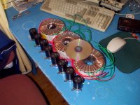
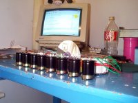
Transformers arived today.. 😀 YAY!!! hm... heatsinks, and a case... hmhmhm case needs to be big enough... and strong enough... transformers weigh 12Kgs total... they are like 130mm in diameter and 65mm high... I believe they are the same size as a 500VA transformer... the windings on them are very spread out... hmm
ukram said:The full specs for my LM4780 amp are here: http://hepso.dna.fi/misc/lm4780/lm4780_amplifier.html
PCB is euro size, and with low profile elcaps it is possible to stack a few of them into relatively small space.
An externally hosted image should be here but it was not working when we last tested it.
you selling PCBs? 😀 😉 or should I read your side abit more lol...
EDIT: yep... shoulda read it.. 😛 lol
Fuses
Why is it wrong ? By switch up high inrush current blow this fuse ( if have correct size ). If is oversized, is it for nothing, because by failure of amp all charge of capacitor " flow " without any limitation. Correct is fuse on primarily side of transformer and second fuse before voltage rail ( behind main capacitor ).
Why is it wrong ? By switch up high inrush current blow this fuse ( if have correct size ). If is oversized, is it for nothing, because by failure of amp all charge of capacitor " flow " without any limitation. Correct is fuse on primarily side of transformer and second fuse before voltage rail ( behind main capacitor ).
I doubt that in the case there is a large DC voltage on the output, fuses inserted in the rails of the amp will blow quick enough to prevent the demise of the speaker, or at least damage. However some people do it anyway, maybe more for psychological peace of mind. I do not like to put fuses in rails or speaker lines (this is also common in some amp designs and serves exactly the same purpose - to prevent the speaker blowing up on high amounts of DC at the output), so I avoid it completely.
In any case, putting a fuse in will definitely limit the kind of currents that pass through the output stages, in case of low impedance speakers the fuse can go off in the middle of the session, even if all the other components are capable of correctly handling the transients. A well-designed amp should have enough room to handle transients, and quite a lot more.
Catastrophic failure, say like failure of the output transistor will probably ensure the speaker dies before a fuse can blow. A better way to correct would be to use active protection. Increases complexity, but if you want protection it's better to be well-protected.
As for the primary, the fuse should always be of the correct rating, but should be a slow-blow type to prevent fusing at switch-on, particularly for toroids. Upupa is right in saying that fusing the secondary AC is not advised, because the caps on the supply can pull some serious current, upto tens of amperes. Putting a 15-amp fuse on a gainclone will neither protect the gainclone, nor its speakers, nor the amp.
but the problem is 8 channels, and 750VA of transformers... if one channel get shorted or the chip dies, I don't think its going to take out the slowblow mains fuse too quickly...
I used 250 VA toroidal tranformer in my LM3886 amp. I had to use at least 3A (230 V mains) "slow blow" fuse to avoid blowing it just with the transformer startup current. Then i used a current limiter on the primary AC, which softened the startup so much that a 500 mA fuse could be used on primary. 3A*230V = 690W into the speaker...
it all well and good for a 2 channel amp.. but with these 8 channels, I'd still want a 4 amp fuse..... which isn't going to protect much is one amp chip fries, and nothing more.. 😛
I think its time to find some heatsinks...
and fans.... and an enclosure, and some PCBS...
grrrr.. PCBs... hmmmm
maybe I should just pay the cash and get the PCBs from ukram.....

EDIT: Thats $US100 for the 4 boards I need... thats $136.205 AUD
wow, the american dollar is doing really poorly.. lol
$140!!!! that would make it the most expensive part of the whole amplifier.... hmmm
maybe I'll just have to try p-p....
maybe I can try making my own PCBs... I mean, I'm sure I could set myself up and make the 4 PCBs for less than $140....
and fans.... and an enclosure, and some PCBS...
grrrr.. PCBs... hmmmm
maybe I should just pay the cash and get the PCBs from ukram.....
EDIT: Thats $US100 for the 4 boards I need... thats $136.205 AUD
wow, the american dollar is doing really poorly.. lol
$140!!!! that would make it the most expensive part of the whole amplifier.... hmmm
maybe I'll just have to try p-p....
maybe I can try making my own PCBs... I mean, I'm sure I could set myself up and make the 4 PCBs for less than $140....
This chip looks most interesting, and promising (although I don't have enough knowledge by any means to say that, but it looks good 😛).
What sort of a transformer should I expect to use for one channel, bridged? to get around 100 watts, or possibly the full 120 watts?
I'm trying to decide on a project for next year, and this might be one possibility! Although I'm not sure if I should do 2 chip amps, or if I should go with somethin like aleph 5 (already got heatsinks for it!) or p3a.
Certainly looks interesting I must say, and VERY simple!
- Status
- Not open for further replies.
- Home
- Amplifiers
- Chip Amps
- My 8 channel LM4780 power amplifier.. :D