Thank Savu,
then normaly,fixed pwm with big capacitor on high voltage cell...I think.
this is usefull for big current output, sure...not pure voltage.🙂
regards
then normaly,fixed pwm with big capacitor on high voltage cell...I think.
this is usefull for big current output, sure...not pure voltage.🙂
regards
at this power, in pro audio, big current is what you need to drive multi kw subwoofers 🙂
and in bridged class D, no need high voltage. In fact low voltage is better because you can use faster and more efficient mosfets...
and in bridged class D, no need high voltage. In fact low voltage is better because you can use faster and more efficient mosfets...
Yes,I agree.
I develop very similar for bridge high-power (sub), full bridge psu with fixed pwm, very big current output. problem is power factory, EMC not agree with this, many EMI conduction Vs. AC-Line🙂
Regards
I develop very similar for bridge high-power (sub), full bridge psu with fixed pwm, very big current output. problem is power factory, EMC not agree with this, many EMI conduction Vs. AC-Line🙂
Regards
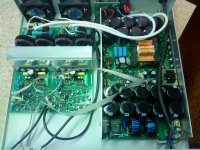
I am waiting PCBs 4KW(EE65 CORE) and 6KW (EE100 CORE), Both arrives in 10 days, all parts are waiting assembly.
As per my details and calculations. its only a timing issue, thats all.
Thanks savu
As per my details and calculations. its only a timing issue, thats all.
Thanks savu
Attachments
Last edited:
Good to know ...
still struggling with 1KW. My last smps some years ago was 3KW but EMI was a mess compared to what I am trying to do now.
now I want to do better EMI and efficiency smps.
Regards,
still struggling with 1KW. My last smps some years ago was 3KW but EMI was a mess compared to what I am trying to do now.
now I want to do better EMI and efficiency smps.
Regards,
It looks you are unable to get help here for some reason. or you are OK?
SMPS success are costy by all means.
Thanks
SMPS success are costy by all means.
Thanks
Yes you are right... you get info, and how you use it it's youre problem.
most of the people here that know what they are talking about are freelancers, have their own company and so on.
I for example am the best (they say) company engineer in Europe regarding the auto wire harness industry.
even if i want to teach all of my experience and knowlage to someone else it will take a couple of years because i do programing, embedded solutions, process engineering, procurement, prototype development and so on.
My job is with thees things in mind secured for the next years.(even if it is payed awful).
The problem is that everyone wants profit after some years of hard work. diy-ers are OK but most of the ppl on this site just want to copy and sell.
Best regards,
Looks like a lot of people have copied the QSC and Crest SMPS schematics.
sam
Well, using an LC or LLC tank over the output transformer is a well known technique that you can see on any reference book, I dont think that the following brands are simply copiers by doing just that:
CREST AUDIO
QSC
ECLER
PKNC
MATRIX
MC2
C-AUDIO
CROWN
YAMAHA
CHEVIN RESEARCH
RAM AUDIO
MACKIE
BEHRINGER
PEAVEY
myself
ETC...
Andy F, you work for PWM-AUDIO?😀
I have seen this smps somewhere else also.🙂
Hi Workhorse, sorry but it is not ethical to answer commercial questions on an open forum, anyway you can easily find me by mail as I dont have any problem to talk with you privately.
Being involved in Andy's project, I cannot let spread such bad publicity. Yes it's a SMPS with resonant tank but hey it's a very common topology that QSC did not invent (for the little story, QSC first SMPS was done by an external freelance engineer, not by QSC team).Looks like a lot of people have copied the QSC and Crest SMPS schematics.
sam
Schematic, PWM frequency, protections, parts, layout, everything is different in Andy's project. Andy's SMPS features also MCU, PFC, thermal tracking and floating outputs that are not present in QSC nor Crest. The true is that Andy's SMPS was build from scratch with very specific requirements, not to copy someone's job...
Last edited:
Damn ... Nikula didn't answer (the SMPS owner) on his post.
Hoped it was yours. Well I will need to buy some books to see how to calculate capacitor banks for LLC resonant tank calculation.
Best regards,
Savu Silviu
Hoped it was yours. Well I will need to buy some books to see how to calculate capacitor banks for LLC resonant tank calculation.
Best regards,
Savu Silviu
Well I will need to buy some books to see how to calculate capacitor banks for LLC resonant tank calculation.
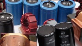
I would say, on the photo is NOT a smps with LLC resonant tank. For me it is more like a smps with series resonant LC tank, like in prototype by AndyF... 🙄 For me "LLC" means, that the resonant tank contains two separate inductors and one capacitor, additionally to the output transformer. Sure, there are topologies with weak coupling of the secondary in output transformer, so that the transformer's primary acts like a separate inductor, but it is already more complex variation, I think... 🙂
About various resonant topologies: http://scholar.lib.vt.edu/theses/available/etd-09152003-180228/unrestricted/Ch4.pdf
EDIT: it seems to be patented: http://www.freepatentsonline.com/6344979.pdf 🙁
Sorry my bad ...
For me LLC ment L,Primary leacage inductance,Capacitor but I found out that is called SRC (series resonant converter).
Thanks for the PDF by the way ...
I found out how LLC works.
My goal is to test a ETD44 core from top to bottom to se exactly how much power I can draw from it by using diferent wire (litz or magnet), diferent topology (halfbridge, fullbridge, etc), different winding structure, different Bmax (for different operating temperature), different switching frequency, etc.
In short words I want to draw the life of an ETD44 core, to take it to the limit.
But the most important thing is to learn a thing or two in this process of benchmarking.
Best Regards,
Savu Silviu
I would be interested in 2 units
Hi Andy,
Could you contact me pls? I would be interested in 2 4Kw supply units with 4 outputs:
+40 - 0 - -40V 3,8Kw
+60 - 0 - -60V 200W
Regards...Marcel.
Hi Andy,
Could you contact me pls? I would be interested in 2 4Kw supply units with 4 outputs:
+40 - 0 - -40V 3,8Kw
+60 - 0 - -60V 200W
Regards...Marcel.
Andrew
Nice work,
I am looking for such power supply from long time, Can you tel me price, Voltages available?
I need it to power my 4 CH class-d Amp 😀
Nice Work...
Nice work,
I am looking for such power supply from long time, Can you tel me price, Voltages available?
I need it to power my 4 CH class-d Amp 😀
Nice Work...
- Status
- Not open for further replies.
- Home
- Amplifiers
- Power Supplies
- My 4Kw smps finished