This is my first tube amp I have finished before.
I recently buy two new Philip jan 5687WB to replace the old tube. And I find the the sound is strange as well as the voltage.
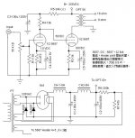
1. The plate volatge of the input tube section for one channel is 49v while the bias in the output tube section is 7.4v (seem quite less than that posted in the drawing=10v) while the voltage of the output tube section for the other channel is 56v and the bias is about 6v (more less than that posted in the drawing=10v). When I swap the 5687 for the two channel. These voltage swaped too. It seems to be a problem about the two 5687. But I don't know whether this different is reasonable for 2 new tubes.
Note: I only get 244v on the B+ from my power supply using 5AR4 rectifyer tube and CLCLC+RCx2(to separate B+ for each channel).
2. I have some questions about the voltage in the drawing. Firstly the 50V plate volatge in the input tube section seem quite small. Secondly, the bias voltage of 1v in the input tube section seem smaller than that calculated from the plate load voltage and plate resistance. What I have got is about 1.7v. Can any one tell me what should be the proper bias and plate voltage for the input and output tube section in this design.
3. What modification can I made to increase its output power. My 100VA power Tx have 2x(3.15v-0-3.15v)3A+1x(2.5v-0-2.5v)3A+260-230-0-230-260v tapping and I am now using the 230v-230v tapping for B+. My output tx tapping is labeled with 10W and tapping of B+/SG2/3.5K/5K & 4/8/16 Ohm.
Thanks for your help.
I recently buy two new Philip jan 5687WB to replace the old tube. And I find the the sound is strange as well as the voltage.
1. The plate volatge of the input tube section for one channel is 49v while the bias in the output tube section is 7.4v (seem quite less than that posted in the drawing=10v) while the voltage of the output tube section for the other channel is 56v and the bias is about 6v (more less than that posted in the drawing=10v). When I swap the 5687 for the two channel. These voltage swaped too. It seems to be a problem about the two 5687. But I don't know whether this different is reasonable for 2 new tubes.
Note: I only get 244v on the B+ from my power supply using 5AR4 rectifyer tube and CLCLC+RCx2(to separate B+ for each channel).
2. I have some questions about the voltage in the drawing. Firstly the 50V plate volatge in the input tube section seem quite small. Secondly, the bias voltage of 1v in the input tube section seem smaller than that calculated from the plate load voltage and plate resistance. What I have got is about 1.7v. Can any one tell me what should be the proper bias and plate voltage for the input and output tube section in this design.
3. What modification can I made to increase its output power. My 100VA power Tx have 2x(3.15v-0-3.15v)3A+1x(2.5v-0-2.5v)3A+260-230-0-230-260v tapping and I am now using the 230v-230v tapping for B+. My output tx tapping is labeled with 10W and tapping of B+/SG2/3.5K/5K & 4/8/16 Ohm.
Thanks for your help.
Attachments
Can you post the voltages present with the old tube, and was it a 5687 or the chinese equivalent?
Matching variations of 10% or more between sections is not unusual in these.
Consider the possibility that these are "duff" tubes and not representative. As a matter of practice I always buy more than I need and if there is significant variation I grade and select the best for ultimate use. (You can do this in your circuit by just choosing the ones that operate closest to your target values.)
IMO the philips ecg (really sylvania) version of this tube is nothing special, but unlike some older, better sounding rca types I have tried, it does not seem subject to filament hum.
Without doing any analysis (and I don't have the time right now, sorry) I can't tell you whether or not the operating points are seriously off.
One thought though is in regards to R5 - is that resistor shared between the two channels? The "(s)" makes me wonder - the supposed 2.1 mA operating point for the first stage does not quite add up with the other resistor values shown in the schematic. Check to see whether or not the second stage is drawing grid current by inserting a small series resistance (say 1K) with the grid of the second stage and seeing whether or not there is a voltage drop across it.
Note that grid stopper resistors are always a good idea with the 5687 - 1K should be fine, mounted right at the grid pin on the socket.
50V for the plate does seem a bit low... OTOH given the limited drive voltage required I expect this is not disasterous.
I generally like to use these with a typical plate current of about 10mA for voltage amplification. The output stage is running at 20mA which is about the limit given the voltage across the output triode.
Slightly more B+ would not hurt, and I would use the higher voltage taps and make adjustments to the supply circuit to get it in the ballpark of 255V.
I would adjust the value of the first cathode resistor to get the plate voltages down into the ~50V range in the first stage, making them smaller to increase the plate current. (Assuming that you have not made a mistake somewhere and miswired or used a wrong value component.)
Depending on chosen load and operating point it might be possible to get a little more power output, probably at the expense of linearity. I wouldn't expect more than about 400mWrms and I would use a load of >3.5K.
Finally as above get some more 5687 to experiment with! They aren't that expensive..
Dear kevinkr
I think that should be separate for the two channel.
I think that there should not be grid current on the output tube as the bias is at least -6v.
What do you think should be the appropiate volatge for the input and output tube?
Thanks
One thought though is in regards to R5 - is that resistor shared between the two channels?
I think that should be separate for the two channel.
Check to see whether or not the second stage is drawing grid current by inserting a small series resistance (say 1K) with the grid of the second stage and seeing whether or not there is a voltage drop across it.
I think that there should not be grid current on the output tube as the bias is at least -6v.
What do you think should be the appropiate volatge for the input and output tube?
Thanks
I mentioned the possibility of grid current in the second stage because the currents and voltages you cite in the first stage do not seem to add up, the excess current must be going somewhere.. (Or your measurements are bogus.) I would still check and see whether or not that was the case as I suggested in the previous post.
Check for high frequency oscillation as well.
Grid stopper resistors are a good idea with the 5687, I never use this tube without them.
I am not going to suggest new working points for the circuit, the ones indicated seem reasonable to me. You need to investigate why the values you get are so far off the mark. DC coupled designs do tend to be trickier in this regard as the working point of the output stage is very dependent on the voltage present on the plate of the preceeding stage as well as the overall supply voltage. The values mentioned in the schematic will differ significantly if your power supply voltages are slightly different.
Again having a selection of different tubes would help. First step would be to get some more 5687. Also you never did answer my first question about the voltages present with the original tubes or are the philips the first ones you have tried in this circuit? I'd measure all voltages in the circuit including the supply voltages, and the supply decoupling networks and post them here.
- Status
- Not open for further replies.