Yes every Channel has the same Transistors in and all do the same.
I have the Transistors with the Y hfe factor. for NPN and PNP.
I have the Transistors with the Y hfe factor. for NPN and PNP.
The hfe isn't a problem.
What are the positive and negative regulated voltages on the op-amp power supply pins?
What are the positive and negative regulated voltages on the op-amp power supply pins?
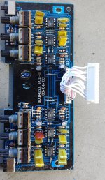
+/- 30 Volts from the PSU, and for the Control circuit it are the 15 Volts + and - with a little bit of difference but they are coupled paralell so every channel gets the same.
The exact values are on the Pictures in the second post.
The exact values are on the Pictures in the second post.
Those are incomplete and useless (to me) without them being on a usable diagram.
You have more than ±75v. Why is that in this amp?
You have more than ±75v. Why is that in this amp?
The Supply rails get decoupled and made into the supply for the control circuit.
If I understand u right.
If I understand u right.
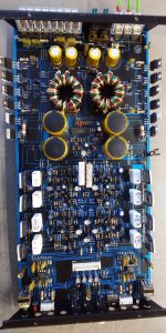
The TL494 and the 4558D´s for the signal modulation.
For the Photo I will need to wait till monday.
For the Photo I will need to wait till monday.
Will measure that points again, at monday.
The TL494 with 12 but the 4558D´s with +/- something volts.
The TL494 with 12 but the 4558D´s with +/- something volts.
I will post a complete picture at monday, In think that will spare us a lot of typing that can just be seen.

- Home
- General Interest
- Car Audio
- MXB 4150i - Problems with the Output Stage