I have made a version of EPS' muting relay for one of my amps.
Same as P33
http://sound.westhost.com/project33.htm
See schematics.
It works, but the relay does sound a bit strange when connecting ... like a buzzing sound.
I have checked the voltage over the coil to see if it is actually controlled properly (nice edge) and it does
http://home20.inet.tele.dk/audio/relay.jpg
First edge is when turning on, and the seconf down going, is when turning off. There seems to be a little after match, but not enough to make the relay trip.
Any ideas .... I would have liked a more clear sounding chnage, but maybe it's just how this relay sounds .... any experience .... ??
(No I don't have any other 12V relay at hand that I could try)
See the video:
http://www.filehosting.org/file/details/29843/MVI_5729.AVI
Anther thing ... aonyone have a less complex circuit for a muting relay?? .... 4 transistors and a bunch of pasives ..... a bit much
Attachments
first, why is there raw unfiltered rectified AC going into the input? that's most likely the source of the buzzing. you might want to filter and even regulate that dc. i understand you want the relay to mute instantly when power shuts off, but there are better ways of doing it.
The purpose of the circuit is to detect loss of AC, when the amp i turned off.
The input is unfiltered to make that detection as fast as possible.
Normally you would see just two diodes, which should work as well ... will probably do without them in the final design.
Take a look at ESP's homepage ......
You say there is better ways ....... could you elaborate ...
Thanks, Baldin 🙂
I don't understand the purpose of the 1n4148 from the 22uF.
The 22uF holds the relay closed in between the pulses from the AC signal.
The first transistor pulls the 100k to near ground voltage every half cycle and then allows the 1uF to recharge in between each AC peak.
If the 100r and the relay (plus it's diodes) were swapped you can add a fast closing and faster off action to the relay.
Is this possible with the PCB you have?
Is that relay current really 650mA? or only 50mA? can you measure the voltage drop across the 100r?
.... as I stated, it's a copy of the P33 .... if it's removed the turn off takes a lot longer and it's too slow to avoid the turn off noise from the amp!I don't understand the purpose of the 1n4148 from the 22uF.
It's only 50 mA .... it's an arrow, ot a 6 😉 ..... I admit, not that easy to see 🙂Is that relay current really 650mA? or only 50mA? can you measure the voltage drop across the 100r?
.... haven't made a pcb for it ... it's still on a proto type board 🙂If the 100r and the relay (plus it's diodes) were swapped you can add a fast closing and faster off action to the relay.
.... faster turn off ... could you draw that up?
Thanks Baldin
Hi,
swap the relay and it's diodes up to the 100r position.
Move the 100r down.
Add an electrolytic from the top of the switching transistor to the bottom side of the relay, where it now meets that 100r.
The cap can be ~22uF and 35v.
It charges up to the supply voltage and when the transistor switches it allows a high current pulse to fire the relay.
The resistor then drops the running voltage just low enough to hold the relay closed in worst case conditions. Because the relay solenoid is passing very little current and the 12V Zener is there to pass the back emf, the relay opens fairly quickly when the transistor opens.
AndrewT
Ok, will try that.
unclejed613
You said there are better ways ... please advice ..
Thanks Baldin 🙂
Ok, will try that.
unclejed613
You said there are better ways ... please advice ..
Thanks Baldin 🙂
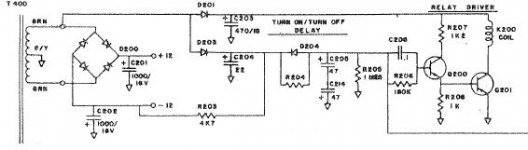
in progress right now.... i have an example of one that worked very well in it's day, including SOA protection for the output devices and DC offset protection, but the heart of it was the time delay circuit that provided a few seconds time delay on startup, and instantaneous shutoff with loss of power/ give me a minute here..... i think i have it on this machine...
ok, found it. this relay circuit is simple and doesn't buzz. R204 was selected at initial test for exactly 3 seconds turn-on delay, and was in the neighborhood of 120K. the wire coming from the lower right went to the protection circuit, that would latch the wire to the -12V rail (through a transistor not shown) if the protection was tripped. this would turn off the relay as well as drain the time constant cap (C205 and C214) and the circuit would begin timing again. when power was shut off, C204 would discharge in 1/10 sec, and D204 would become forward biased and discharge the timing cap to the -12V rail instantly, and the relay would shut off. protection deactivated the relay instantly, power loss within 100mS (which was considered enough time to ignore short power interruptions but was not enough time for the amplifier to develop a turn off thump, because the main power supply caps stayed charged much longer).
Attachments
It works 🙂
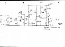
Ok, after some trial and error, I have ended up with this.
It wasn't that easy to get it to turn off fast enough.
For a class-AB amp this would be no problem, as it would take some time for the PSU to loose enough voltage for it to make a plob in the speaker.
The way my class-d amp it makes a noise just after the switch is turned off.
For fastest turn off the trick is:
- Choose C2 as small as possible. The turn on delay is determined by R2-C2.
- Choose R1 as small as possible. At turn off, both C1 and C2 is discharged through this resistor.
- Lower the voltage over C1 as much as possible. I have put in a zenner on 6,3 V for this purpose. The less voltage the less time it takes for C1 to discharge. C2 which determines the turnoff time, will not start discharging before V_C1 is lower than V_C2 minus Vdiode .....
Anyway with the components shown, it works quite well 😀
Attachments

this is a delayed turn on.
There is no instant off circuit.
It waits for the charge to slowly diminish and eventually switches off.
There is no instant off circuit.
It waits for the charge to slowly diminish and eventually switches off.
the circuit i posted had the discharge path through a negative rail, not ground......
I know, and it would of course work a lot faster, but I don't have a negative rail in the circuit (the amp is a full bridge)

Anyway it works good enoughfor my purpose.
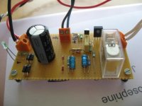
See picture of both + 16 VDC PSU for the gate driver and the realy circuit.
Attachments
- Status
- Not open for further replies.
- Home
- Amplifiers
- Solid State
- Muting Relay ..... buzzing