When the amps inputs are shorted to ground there is no noise!That sounds really odd to me. Silly question but does it do that with shorting plugs in the inputs?
Tried this first as it was the easiest task in the troubleshooting list, and the problem goes away.
Now I guess this means that there is something funky happening at the output of my preamp (DIY Pass B1K) 🤔 (???).
It is weird in that my old power amp (DIY Pass F6) did not have this noise on startup despite having the same preamp (DIY Pass B1K)?
What is the path forward here?
Find the source of the startup noise most likely coming from the preamp?
or
Add a simple muting circuit to the inputs of the power amp?
EDIT:Very interesting, I only get the start up noise when my sub woofer power amp is engaged (i.e. hooked up to the power amps input/preamps output). When I disconnect the sub woofer power amp from the signal chain the noise goes away.
Could the tube power amp and the sub woofer amps current draw upon startup be causing issues?
Last edited:
Do you get the noise if the sub amp input is connected but the sub amp unpowered?
Have you got the volume control before or after the B1 output. In other words is the output impedance feeding both these amps low?
Also to rule out something odd with the power amp you should now try just tying the power amp inputs to ground via a resistor. In other words swap the shorting links for say a 100k. It should still be silent. It rules out the possibility of the power amp doing something weird like bursting into some brief oscillation.
You could use the solution by famous tube guru Dr. Heinrich Von Doofenstein (1914 - 1954) invented in the tube era somewhere around 1934 when researching EL3 triode Einschaltphänomene. He called it "Kurzschluss von Ausgänge beim ein- oder ausschalten von Röhrengeräte" which translates as "output muting of the shorting to GND kind". The simple, cheap and effective invention was introduced at the Paris fair of 1935 and was rewarded with a standing ovation. Strangely the invention was forgotten in the decades after its conception leading to thousands of people experiencing power on/off plops in audio and not knowing what was happening. Fora were visited and people got depressed by such technical tragedy. Many famous designers getting a lot of praise omitted the invention! Generations of audiophiles grew up with farting and plopping devices. Over the years Pavlov dictated that a device not plopping or farting was seen as defective.
Let's honor Dr. Von Doofenstein and simply use micro relays for output muting in source devices.
Let's honor Dr. Von Doofenstein and simply use micro relays for output muting in source devices.
Last edited:
Hey jean-paul, where is the circuit? Do you have an example?
I guess I can always just turn on my sub amp last to mitigate this issue.
(it is so convient now in that I have my whole system plugged in to a power conditioner which is on a smart switch so I can just say to my Google Home "Hey Google, turn on the stereo").
The volume on the B1K is at the input of the circuit. The output impednance of the B1K is 140R!
The power amp inputs have a 100K grid leak on the input. Stays silent with nothing connected to the RCA inputs.
No noise when the sub amp input is connected but the sub amp is unpowered!Do you get the noise if the sub amp input is connected but the sub amp unpowered?
Have you got the volume control before or after the B1 output. In other words is the output impedance feeding both these amps low?
Also to rule out something odd with the power amp you should now try just tying the power amp inputs to ground via a resistor. In other words swap the shorting links for say a 100k. It should still be silent. It rules out the possibility of the power amp doing something weird like bursting into some brief oscillation.
I guess I can always just turn on my sub amp last to mitigate this issue.
(it is so convient now in that I have my whole system plugged in to a power conditioner which is on a smart switch so I can just say to my Google Home "Hey Google, turn on the stereo").
The volume on the B1K is at the input of the circuit. The output impednance of the B1K is 140R!
The power amp inputs have a 100K grid leak on the input. Stays silent with nothing connected to the RCA inputs.
No noise when the sub amp input is connected but the sub amp is unpowered!
So all that points to the sub amp throwing something back at the inputs. Hmm. The B1 circuit I'm looking at shows a 1k series resistor at the output. If your is like this then you automatically have at least 1k output impedance and tbh I think quite a bit more given the 'soft' nature of the FET buffer.
https://www.passdiy.com/project/preamplifiers/b1-buffer-preamp
You could try a simple muting relay across the output of the preamp, one which is normally short to ground and opens after a delay. That way there is no signal degradation due to contacts etc. Dead easy to do with a relay, a FET and a C/R delay. Nothing else needed.
That is the Pass B1
The Pass B1K is different
https://cdn.shopify.com/s/files/1/1006/5046/files/DIY_NUTUBE_PREAMP_Revised_2020-07-25.pdf
But yes thank you Mooly for the excellent advice! That is exactly what I will do. The Pass B1K has a regulated 12V in it I can use for the muting circuit.
Do you have a schematic for the mentioned circuit?
Have a look a the muting circuit of DCB1/Mezmerize that has a muting circuit like a quality device should have but there are others. A handful of parts. The point is to use a micro relay shorting outputs to GND (like the invention of Herr von Doofenstein was) and not relay contacts or even semiconductors in series with the outputs as that can have negative influence on sound quality.
Muting circuits can be a simple or complex as you wish.
Here is a super simple idea using a single FET (a 2N7000 type would be ideal but you could use a bigger power FET). The cap would have to be a low leakage type, not an electrolytic. The Zener is not needed for 12 volt supplies.
Supply appears 10 seconds in here and goes off at 40 seconds.
Looking at your circuit and you could use the 24 volt supply and a small 24 volt relay which would have a high coil resistance. That would need the Zener to protect the FET but might be better than a low voltage version pulling relay current from the resistor/Zener supply of the buffer.

This circuit worked like a charm! Only had 9V relays on hand so used a 2N700 with a 9V supply.Muting circuits can be a simple or complex as you wish.
Here is a super simple idea using a single FET (a 2N7000 type would be ideal but you could use a bigger power FET). The cap would have to be a low leakage type, not an electrolytic. The Zener is not needed for 12 volt supplies.
Supply appears 10 seconds in here and goes off at 40 seconds.
Looking at your circuit and you could use the 24 volt supply and a small 24 volt relay which would have a high coil resistance. That would need the Zener to protect the FET but might be better than a low voltage version pulling relay current from the resistor/Zener supply of the buffer.
View attachment 1167293
I used a 4.7uF electrolytic cap and got 15 second delay, before the relay engaged and moved to the NO contacts. A 10uF electrolytic got me 30 seconds of delay. Why did you suget not to use elctrolytic?
Going to wire it up so common is the audio signal and the NC contacts are the ground.
Why did you suget not to use elctrolytic?
It is because the leakage current would tend to dominate and might even prevent the cap charging enough due to the high value of charge resistor.
Lets say the cap has reached 7 volts on a 9 volt supply. That means you have only 2 volts left across the 10meg (in my example) and that only gives an available current of 2/10,000000 which is less than the leakage current of a typical small electrolytic. So the cap would never even charge.
Ok I will make sure I once again breadboard with the exact components I use to make sure they will work in the circuit once built. Going to pick up a 12V relay today.
I guess the play would be if using elctrolytic to use one that has the lowest leakage current, right?
I guess the play would be if using elctrolytic to use one that has the lowest leakage current, right?
Definitely trial and error to get your timing values if using an electro. A tant might be usable.
Here is a typical data sheet. 3uA or 0.01CV, whichever is highest. 4.7uF with 10 volts across it is (4.7E-6 * 10) * 0.01 which is 0.00000047 which is 47uA. That is worst case, presumably with the cap at its max temp rating.
So lets say we have 5 volts across the 10 meg resistor. That gives us just 0.5 microamps of current available. So the cap could never charge, The leakage dominates. As the voltage across the cap rises (as it charges) the less voltage (and so less current) is available across the 10 meg to charge it.
So trial and error. I would begin with a good quality film cap I think
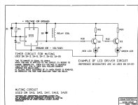
I use this relay module for my projects, you can increase the capacitor value for longer delay.When the amps inputs are shorted to ground there is no noise!

NE555 DC 12V Delay Timer Switch Adjustable Module 0 to 10 Second
Some amplifier from Vincent Audio use relay NC contacts short the input to ground during startup.
Last edited:
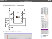
The 555 is a great chip to play around with. This is a circuit I did a couple of decades ago to give a delay to the output of a preamp. The circuit also generates the full delay if the power is cycled on and off quickly and it also has visual LED indication.

The zipped folder has some notes along with the sim.
Contents of folder:

The zipped folder has some notes along with the sim.
Contents of folder:
Attachments
You might find that using the speaker inputs to your sub sounds better anyway than the line input. Modern subs have a controllable LPF on the speaker inputs and present a high impedance. I know one of the subs I own has no LPF on the line input because the mfg is assuming you use that input with a receiver that has digitally managed bass already. Personal taste, I've always had better control and sound from subs using either the speaker inputs or with a digitally managed bass as source. I've never had good luck getting a sub to integrate nicely with a simple 6db LPF analog line out. Booooomy. What kind of analog LPF is feeding the sub line input?
I ended up making the circuit on a little bit of perfboard.Definitely trial and error to get your timing values if using an electro. A tant might be usable.
Here is a typical data sheet. 3uA or 0.01CV, whichever is highest. 4.7uF with 10 volts across it is (4.7E-6 * 10) * 0.01 which is 0.00000047 which is 47uA. That is worst case, presumably with the cap at its max temp rating.
So lets say we have 5 volts across the 10 meg resistor. That gives us just 0.5 microamps of current available. So the cap could never charge, The leakage dominates. As the voltage across the cap rises (as it charges) the less voltage (and so less current) is available across the 10 meg to charge it.
So trial and error. I would begin with a good quality film cap I think
Oddly enough with the 10uF NP cap on the breadboard I got about 30 seconds of delay, once soldered and built on the perfboard it was much less (close to 17 seconds).
I tacked a 4.7uF electrolytic cap in parallel and got the delay time up to 30 seconds.
I wonder if heat from soldering affected the cap in some way, not in a bad way, just altered the leakage current.
- Home
- Amplifiers
- Tubes / Valves
- Mute circuit for startup