So yeah to clear up confusion, I was looking for the 2N2955 PNP replacement as a write up stated that it used 2N2955 and a 2N3055
The 3055 being readily available and the 2955 being impossible to find apart from America and the postage is expensive
Jaycee has alerted me that it's not 2N, it's MJ, so thank you for that
I will find myself a pair of MJ15015/16's as recommended, thank you
The 3055 being readily available and the 2955 being impossible to find apart from America and the postage is expensive
Jaycee has alerted me that it's not 2N, it's MJ, so thank you for that
I will find myself a pair of MJ15015/16's as recommended, thank you
I'm new to transistors so please remember that
Looking at "alltransistors.com" (A place to compare transistors), comparing the MJ15016 to the original MJ2955, the transition frequency is 0.8mhz on the 5016 and 5mhz on the 2955
The forward current transfer ratio is 20 on the 5016 and 5 on the 2955
I assume this does not matter as you've recommended them, I'm not doubting you I'm just learning 🙂
Last edited:
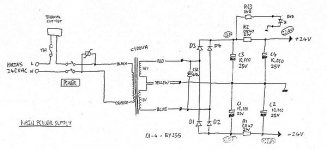
I am very confused as of why my A100's board says that there's a +24v line, when it reads 37v
My transformer is putting out 57v AC, the rectifier is putting out 37V DC
My transformer is putting out 57v AC, the rectifier is putting out 37V DC
Theory that has been created is that my zener diodes have failed, they are supposed to be dumping extra voltage but they haven't been, that's why there's burn marks under the zeners and also why a local resistor next to each zener has popped
Replacements in the mail, will see if that's the fix, replacement MJ15015/16's on the way too
Thank you all for your time and help so far with this journey of fixing my first amplifier, I appreciate it greatly
Replacements in the mail, will see if that's the fix, replacement MJ15015/16's on the way too
Thank you all for your time and help so far with this journey of fixing my first amplifier, I appreciate it greatly
Yeah I am a little confused with the voltage
In order
Transformer 57v AC > rectifier 37v DC (out) > 0.47ohm resistor > large smoothing capacitors (read 37V), then it goes straight into the +24v rail
So I am a little confused what is causing the 37v, I don't know if something after is meant to limit the voltage or if it should be 24v after the very first resistor or 24v coming out of the rectifier
Four resistors had popped (R19, R19, R20, R20) and ZN1 ZN1 ZN2 ZN2 have gotten so hot that they've burned the PCB underneath them (Damage done before my possession)
I replaced the resistors (Seemed to be 330ohm) but they still get very hot if the power supply is turned on, I removed the zeners to test them and two shattered whilst removing due to being brittle, two survived and testing both of them, one of them blocked off anything over 12v but the other let through 28v+ (my lab supply won't go above 28v), I assume they are both meant to be 12v as 28v seems high especially when there isn't meant to be over 24v haha, so I have ordered an assortment of zeners and will be replacing them
One of the PNP output transistors has died, I tried powering the board without the output transistors installed and even though now the large resistors near the capacitors do not get hot, the 330ohm R19 and R20 and the ZDR1/2 still get hot, even with the output transistors not even in the circuit
I assume this is due to the random 37v, but I cannot identify where it is coming from, I have zero references so I can't pinpoint with my limited knowledge, if I could validate that 57v AC out of the transformer is fine or not, or if 37v DC out of the rectifier is normal or not then at least I could target a part for replacement
The transformer is standard as it stays "A100-MULTI" on a sticker underneath the plastic wraps and I don't think anyone has been in here before
Any pointers are really really really welcome, I have no doubt the amp will work after I replace the zeners and my replacement output transistors come, but without the 37v turning back into the 24v it should be then it'll only work for a moment till everything pops again
This is a complicated amp to fix as a first timer, even though it looks basic visually there's a lot of special things going on here, never mind the non-existent schematics
One more quesiton, in this write up it states that the new A100 came with two cooling fans and that it used 38v rails instead of 24v rails like the A1
Well I have an A100 but it says on the motherboard +24v and I only have one fan, yet the transformer and the board do state A100
Are there two revisions of the A100 and I have the first version? (Musical Fidelity A100 | zStereo)
From what I can see and understand the transformer must be around the 18/0/18Vac to give the 24/0/24Vdc stated in the schematics and on the board and unless the toroid is somehow shorted there is no way it will put out 37Vdc or you measuring it wrong (somehow).
The 37V you measure are AC or DC and where are you measuring it ?
If you reading 37V AC before the rectifier(s) that is about right.
The 37V you measure are AC or DC and where are you measuring it ?
If you reading 37V AC before the rectifier(s) that is about right.
Attachments
Last edited:
Some pictures might be a good idea. Apparently the A100 is a beefed up A1 so things should follow.
Your 57VAC from the transformer followed by 37VDC from the bridge sounds as if you are measuring across the transformer's secondary and missing the centre tap, so that sounds right. I think perhaps they increased the power supply voltage. What is the voltage rating on the power supply capacitors?
Your 57VAC from the transformer followed by 37VDC from the bridge sounds as if you are measuring across the transformer's secondary and missing the centre tap, so that sounds right. I think perhaps they increased the power supply voltage. What is the voltage rating on the power supply capacitors?
Like jaycee said something is very wrong because the math don't add up, you say 57V ac so that would be around 28V on each secondary that would give around 37VDC after the rectifier and cap bank.
Again without a schematic or service manual this is a guessing game.
Again without a schematic or service manual this is a guessing game.
According to my previous experience, all those electrolytic capacitors need to be replaced. Because of the high temperature work of A1 all year round, the performance of electrolytic capacitors has probably declined. I have done this work for players many times.
If you cannot find MJ2955, you can use MJ15024/MJ15025 to replace the original power tube. The sound of this pair of power tubes used here will be better than MJ15003/MJ15004.
According to Mark Hennessey, who's about as good an authority on the A1 as you'll find on the net, the A100 model is essentially the same amplifier as A1 but operates in class AB with a hefty 800mA bias current. Obviously, the higher rail voltages mean higher voltage rated components but also more power output with little cost or heat increase.
See related models section here: Hi-Fi › Musical Fidelity A1
See related models section here: Hi-Fi › Musical Fidelity A1
Hey guys, I had a little break!
Getting back to it today, I replaced a few zener diodes, I replaced the op amps as I had some laying around and I installed the new output transistors on the heatsink but have yet to solder them onto the board
Powering on the amp the zener diodes still get very hot, when reading between 24v+ and 24v- I get 73v DC
Measuring the AC voltage that comes out of the transformer I am reading 58v AC between the red and blue wire
Out of the full bridge rectifier I get 37v DC


Do you happen to know what is meant to be knocking the 38v down to 24v? I'm not the best at reading schematics I must admit, but something isn't reducing the power from 38 down to 24 and I believe that to be my issue with the amp
Once I sort out what isn't knocking it down to 24v, I can then replace a few parts and get it working again
I found out yesterday that I had a dead BC560C, replacement coming today
The answer is nothing.
The power supply is not regulated so what you get in the capacitor bank is what the transformer delivers to the rectifier(?) x 1.4 or around 18/0/18Vac or 36Vac from both coils for a 24/0/24Vdc rails but you are getting around the 36/0/36Vdc rails so the transformer is delivering around 26/0/26Vac to the rectifier(s).
There are a few options
1st the transformer is correct and you have +/-36Vdc rails
2nd the transformer is somehow shorted and delivering more voltage than it should (very unusual but I have seen it before)
3rd Someone replaced it with the wrong one (???)
4th you have to consider that the transformer and rails voltages are the correct ones and that the info from Mark Hennessy doesn't apply to your amp
You could try higher power zeners in that position ( like 1W ones) or higher resistance for R13/14 (I'm not expert in that field).
It's not easy if you don't know the history of that amplifier, you never know where it has been before and it what hands.
Last edited:
I'm taking a break from trying to fix it, for now, I've been side tracked just a tinnnyyy bit
I'm currently replicating the PCB 1:1 in EasyEDA, mostly because I have a short attention span and I spread my focus onto many projects at once, but secondly because it means I can get a black board printed for my A100 haha
I'm copying it 1:1 although I'm moving a couple components a mm or so, just to make things more aesthetically pleasing and symmetrical
Where a couple zeners and resistors got terribly hot, it's damaged/peeled away a handful of solder pads and I would feel uncomfortable scratching back a trace or bridging it to another pad in line, it works and it's acceptable but it's not as nice as an intact pad!
If anyone has any recommendations for modifications or fixes that aren't too far out of my league then please let me know now whilst I'm birthing this monster
The only modification so far will be a 12v or 24v DC connector/pins somewhere on an empty space of the board so that I can drop in an LM2576 buck converter as a daughterboard so that I have a variable voltage output, my plan is to 3D print an adapter for the stock fan so I can drop in a modern day axial fan for higher CFM but lower noise output
This drop in module would be optional and wouldn't be needed to have the PCB functional
So if anyone has ANY recommendations of tweaks, mods, upgrades please let me know as I'm hoping to finish this PCB in the next week (High hopes haha)
You still didn't answer the question (maybe you just don't want to) .
A1 or A100 ?
In your last post you mention "stock fan" so it looks like you have a A100 or a later A1 after they jack up the power supply and added a fan to get power to 50W (original A1 was 20W) so all this back and forth was just an exercise in wasting time.
Anyway I would tell you to get this one running as it should before doing anything else.
Good luck and have fun
- Home
- Amplifiers
- Solid State
- Musical Fidelity A1 capacitors, resistors ect