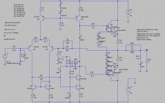
The reverse engineered power amp circuit of A1 2008 edition is published in a Chinese magazine. The output devices are STD03P/N. I simulated in LTspice with discrete Darlington. The performance is very promising. The amp uses two-pole compensation to achieve good THD performance. I am going to build a test board.
The simulation circuit is shown here. R25 and 26 are not present in the actual circuit.
The simulation circuit is shown here. R25 and 26 are not present in the actual circuit.
Attachments
The reverse engineered power amp circuit of A1 2008 edition is published in a Chinese magazine. The output devices are STD03P/N. I simulated in LTspice with discrete Darlington. The performance is very promising. The amp uses two-pole compensation to achieve good THD performance. I am going to build a test board.
The simulation circuit is shown here. R25 and 26 are not present in the actual circuit.
Very interesting Panson and thanks for sharing with us. It is no a secret that I love the sound of the STD03's 😀 Do you know why they use additional D4 and D5? Can't the diodes inside the STD's provide sufficient voltage drop for high bias? (I never biased the STD03's so high so I have no clue).
I will follow you close with this project, since I can learn a lot from your experiences. Especially the biasing, because I failed to let the STD03's work well with high bias levels. I look forward to see how you going to make it work 😀, but I am confident you will succeed.
Good luck!
With kind regards,
Bas
Do you know why they use additional D4 and D5? Can't the diodes inside the STD's provide sufficient voltage drop for high bias? (I never biased the STD03's so high so I have no clue).
Hi Bas,
D4 and D5 are used for biasing the output in Class A. I will be very careful with STD in high bias.
Panson
The simulation circuit is shown here. R25 and 26 are not present in the actual circuit.
Curious about those two input transistors. Is there a special reason to use ZTX757s and not to degenerate them with R25 and R26? As far as I could recall from Doug Self's book, the only downside for degenerating the input LTP was a noise penalty. But you can't be aiming for ultra-low noise here as your feedback components are fairly high impedance and you're running only 700uA into the tail. Are you intending to run at much higher voltages? - that would explain choosing 300V transistors for the input stage.
Hi Bas,
D4 and D5 are used for biasing the output in Class A. I will be very careful with STD in high bias.
Panson
Forgive me for being so stubborn. I have no doubt Musical Fidelity knows what they are doing, I just want to understand "how" that is why I ask so much. I just don't understand how they keep the thermal tracking stable, because it is clearly stated and showed in the datasheet of the SAP devices that thermal tracking isn't good anymore above 80mA. I would be more then happy if the solution comes out here on the forum, so I can finally bias my own STD03's higher as well 😀 Measurements I did showed, that the THD get significant lower with high bias level. I was just never able to get it thermal stable by only rely on the thermal tracking diodes.
With kind regards,
Bas
Curious about those two input transistors. Is there a special reason to use ZTX757s and not to degenerate them with R25 and R26? As far as I could recall from Doug Self's book, the only downside for degenerating the input LTP was a noise penalty. But you can't be aiming for ultra-low noise here as your feedback components are fairly high impedance and you're running only 700uA into the tail. Are you intending to run at much higher voltages? - that would explain choosing 300V transistors for the input stage.
I actually got the same question. However, this is the circuit shown in the article. I did not make any change except output Darlington by discrete. It may be due to the author did not make the reverse engineering correctly. However, there are many commercial amps not following D. Self's book.
Well, I will compare the performance between with and without degeneration when I build a prototype (and simulation).
I actually got the same question. However, this is the circuit shown in the article.
Cool 😛. I'd be inclined to make some improvements myself if laying out a PCB. Definitely include spaces for those resistors - they'll improve the slew rate and may even help in RF rejection (my favourite hobby horse😀). I feel certain that other Zetex (Diodes) transistors will do the job better than those 757s - their hFE below 1mA IC could be below 40.🙁
Hi Bas,Forgive me for being so stubborn. I have no doubt Musical Fidelity knows what they are doing, I just want to understand "how" that is why I ask so much. I just don't understand how they keep the thermal tracking stable, because it is clearly stated and showed in the datasheet of the SAP devices that thermal tracking isn't good anymore above 80mA. I would be more then happy if the solution comes out here on the forum, so I can finally bias my own STD03's higher as well 😀 Measurements I did showed, that the THD get significant lower with high bias level. I was just never able to get it thermal stable by only rely on the thermal tracking diodes.
With kind regards,
Bas
Do you think that the STD used as conventional Darlington (omitting diode stack) will have problem for high bias? If the problem is solely due to diode stack temp coeff difference from that of the transistor, we should be able to find a proper diode stack current for good thermal tracking.
On the other hand, is Darlington not good for Class A operation since the driver is "over" heated by the output transistor. Have you seen/tried other Darlington for Class A operation?
Panson
Hi Bas,
Do you think that the STD used as conventional Darlington (omitting diode stack) will have problem for high bias? If the problem is solely due to diode stack temp coeff difference from that of the transistor, we should be able to find a proper diode stack current for good thermal tracking.
On the other hand, is Darlington not good for Class A operation since the driver is "over" heated by the output transistor. Have you seen/tried other Darlington for Class A operation?
Panson
Dear Panson,
I've never seen a Darlington for class A operation till you showed me the A1 2008 edition schematics. I was aware though that Musical Fidelity builds even bigger class A amps with the STD03 device.
In a very optimistic attempt to make my own STD03's class A I failed the hard way, and blow them up many times. Not because of oscillation, but because of thermal run away. The amp goes into a thermal loop and heat up very rapid.
But, assuming the A1 2008 edition works good, it seems it must be possible with the STD03's. I just don't have the skills to make it happen in class A with those devices. I hope you provide the solution 😀
EDIT: Maybe I overlooked it, but a bit tricky is indeed we don't know the hFE and the current ability of the build in drivers. Makes it indeed more tricky. But then again Musical Fidelity did it... 😀
With kind regards,
Bas
Last edited:
Hi Bas,
D4 and D5 are used for biasing the output in Class A. I will be very careful with STD in high bias.
Panson
High Bias has STD ? .......................... 😱
Sorry I am not a Native English speaker (as shows off.. 😀). I mean a high biased STD darlington device 😀 Clear? 😀High Bias has STD ? .......................... 😱
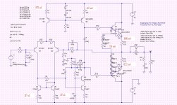
DC values
Here are some DC operating points. The differential input stage is in balanced condition where each transistor shares half the tail current. VAS current is 4.12 mA. Output stage is biased at about 600 mA. The article mentions the output stage bias current is 680 mA, +/-10 mA.
Here are some DC operating points. The differential input stage is in balanced condition where each transistor shares half the tail current. VAS current is 4.12 mA. Output stage is biased at about 600 mA. The article mentions the output stage bias current is 680 mA, +/-10 mA.
Attachments
In a very optimistic attempt to make my own STD03's class A I failed the hard way, and blow them up many times. Not because of oscillation, but because of thermal run away. The amp goes into a thermal loop and heat up very rapid.
Hi Bas,
How much bias current did you try? You simply use a trim pot to adjust the bias level?
Panson
Just some pure paper work.
Here is an app note from Zetex for reference (http://www.diodes.com/_files/design_note_pdfs/zetex/dn4.pdf). It shows temp coeff of BJT, diode and Schottky. Vbe temp coeff and diode Vd temp coeff are similar (-1.9 ~ 2.2 mV/C). Schottky is -1.2 mV/C. STD03N has one silicon diode. This diode compensates on Vbe temp coeff. STD03P has five schottky. They compensate 2.5 Vbe. STD03N+P have four Vbe. However, the diode stack only compensates for 3.5 Vbe temp coeff. We end up an under compensated system if no extra mechanism is included.
Here is an app note from Zetex for reference (http://www.diodes.com/_files/design_note_pdfs/zetex/dn4.pdf). It shows temp coeff of BJT, diode and Schottky. Vbe temp coeff and diode Vd temp coeff are similar (-1.9 ~ 2.2 mV/C). Schottky is -1.2 mV/C. STD03N has one silicon diode. This diode compensates on Vbe temp coeff. STD03P has five schottky. They compensate 2.5 Vbe. STD03N+P have four Vbe. However, the diode stack only compensates for 3.5 Vbe temp coeff. We end up an under compensated system if no extra mechanism is included.
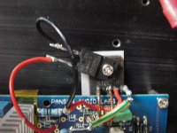
I am testing STD in high-bias level/Class A operation. Since the A1 clone prototype is not ready, I use my Compact 49811 + STD test unit. A discrete diode and trim pot are in series with the STD diode stack. The discrete diode is attached to STD03P for thermal tracking. The operating rail is +/- 35 VDC.
I initially set the bias to 200 mA (i.e. 44 mV across 0.22R emitter resistor). At the time bias level set to 200 mA, the heatsink (from cold start) is about 28 C. It gradually increases to 36 C. The bias also increases to 259 mA. I then feed a sine wave to have output 10 V peak into 8 Ohm. When the heatsink temperature is 42 C, I remove the input signal to measure bias again. The bias is 340 mA. It is obvious that we have an under compensated bias system.
In order to increase the temp coeff (more negative actually), I then insert one more diode. With the trim pot at zero ohm, I have about 450 mA per STD. The heatsink temp is about 38 C at the time bias is measured. The bias keeps moving up slowly. It reaches 504 mA with heatsink temp equal to 49 C. Compared to previous case, it has improved thermal tracking.
340/259 = 1.31, delta temp: 42 - 36 = 6 C
504/450 = 1.11, delta temp: 49 - 38 = 11 C
Well, no thermal runaway happens so far. Test is continued.
Attachments

Hi Bas,
How much bias current did you try? You simply use a trim pot to adjust the bias level?
Panson
Dear Panson,
As advised by the data-sheet I sett the pre bias at 2.5mA and the Output-stage bias at 120mA, and there it got wrong... As soon I go over the 80mA I get thermal instability. Because if the pre bias shifts a little bit, the output bias shift a lot. I figured out it could work if you add extra compensation with a diode or VBE multiplier and compensate the pre-bias. But then the STD03's will loose their charms as being devices that don't need a VBE multiplier or extra components.
With kind regards,
Bas
I am testing STD in high-bias level/Class A operation. Since the A1 clone prototype is not ready, I use my Compact 49811 + STD test unit. A discrete diode and trim pot are in series with the STD diode stack. The discrete diode is attached to STD03P for thermal tracking. The operating rail is +/- 35 VDC.
I initially set the bias to 200 mA (i.e. 44 mV across 0.22R emitter resistor). At the time bias level set to 200 mA, the heatsink (from cold start) is about 28 C. It gradually increases to 36 C. The bias also increases to 259 mA. I then feed a sine wave to have output 10 V peak into 8 Ohm. When the heatsink temperature is 42 C, I remove the input signal to measure bias again. The bias is 340 mA. It is obvious that we have an under compensated bias system.
In order to increase the temp coeff (more negative actually), I then insert one more diode. With the trim pot at zero ohm, I have about 450 mA per STD. The heatsink temp is about 38 C at the time bias is measured. The bias keeps moving up slowly. It reaches 504 mA with heatsink temp equal to 49 C. Compared to previous case, it has improved thermal tracking.
340/259 = 1.31, delta temp: 42 - 36 = 6 C
504/450 = 1.11, delta temp: 49 - 38 = 11 C
Well, no thermal runaway happens so far. Test is continued.
Excited! 😀 Would be interesting to try it with the LME49810, and insert the discrete diode in the bias string with the bias pins of the LME49810.
With kind regards,
Bas
- Status
- Not open for further replies.
- Home
- Amplifiers
- Solid State
- Musical Fidelity A1 (2008) power amp clone project