Hi all, got myself a MF A5 intergrated amplifier thats using the sap15 transistors.
These transisitors have the emitter resistor built in and are prone to failing. Ive read that you can lift a leg on these transistors and put your own cement 0.22ohm resistor in its place.
Question is can anyone advice what leg to lift and where to solder new resistor please, or any pictures of this done or drawings would be fantastic!
Thanks inadvance
Richard
Here is the data sheet on it. If the resistors have failed, the odd are so has the Darlington pair.
datasheet SAP15
datasheet SAP15
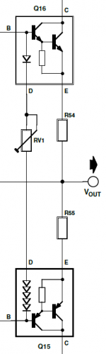
Lift the "E" leg, and put your own emitter resistor from "S" to "E".
But why, if it works, leave it IMO ¯\_(ツ)_/¯
But why, if it works, leave it IMO ¯\_(ツ)_/¯
They have not failed, i just dont want them to.Here is the data sheet on it. If the resistors have failed, the odd are so has the Darlington pair.
datasheet SAP15
I get that, but doing this mod will make the transistor a lot more reliable is my thought😕Lift the "E" leg, and put your own emitter resistor from "S" to "E".
But why, if it works, leave it IMO ¯\_(ツ)_/¯View attachment 763232
Your call. My approach is usually to not fix things unless they are, well, broken.I get that, but doing this mod will make the transistor a lot more reliable is my thought😕
Your call. My approach is usually to not fix things unless they are, well, broken.
What watt resistor would you use? The amplifier has 2 pairs for each channel and is rated at 250w per channel. I see how they are unreliable if you compare the size of the eg 5w cement compared to the transisitor one built in!
They will failed if your are running them continuously at high temperature.Did read some on the internet that they will fail but never mentioned what cause the failing, yet I doubted those who claiming failure, were really using them or not.
Am a big fan of those SAPs, make my layout neat and lesser components, but sourcing them might be a pain.They already replaced by a smaller (but standard package) STDs, which the internal resistor already remove and one pin gone.
Am a big fan of those SAPs, make my layout neat and lesser components, but sourcing them might be a pain.They already replaced by a smaller (but standard package) STDs, which the internal resistor already remove and one pin gone.
Someone needs to check my math but this is what I came up with...
At full power:
* 250w/4ohm output.
* 2 pairs (so, 125W per pair).
* That's about 24v RMS into 4 ohms
* Each transistor does about half the waveform, assuming class AB. That's 12v RMS.
* 12V RMS into 4 ohms is 3A
* 3A / 0.22 ohms is a drop of 0.66v
* Dissipation across 0.22 ohm at 0.66v is 2W
5W seems like a good choice.
Keep in mind cement resistors are designed to dissipate 5W directly into air. The IC is mated to a heatsink so it can easily dissipate more heat than the package size would suggest. For example TO220 devices are able to dissipate over 50W into a suitable heatsink.
Here is the data sheet on it. If the resistors have failed, the odd are so has the Darlington pair.
datasheet SAP15
The resistor inside this transistor is known to fail early with the darlington being fine. Replacing the build-in R with an external one is a known cure.
The follow-up devices to the SAP series, STD03N and 03P, look exactly the same but miss the internal R, for just this reason.
Jan
Attachments
Last edited:
Someone needs to check my math but this is what I came up with...
At full power:
* 250w/4ohm output.
* 2 pairs (so, 125W per pair).
* That's about 24v RMS into 4 ohms
* Each transistor does about half the waveform, assuming class AB. That's 12v RMS.
* 12V RMS into 4 ohms is 3A
* 3A / 0.22 ohms is a drop of 0.66v
* Dissipation across 0.22 ohm at 0.66v is 2W
5W seems like a good choice.
Keep in mind cement resistors are designed to dissipate 5W directly into air. The IC is mated to a heatsink so it can easily dissipate more heat than the package size would suggest. For example TO220 devices are able to dissipate over 50W into a suitable heatsink.
I cant comment on IF thats correct, but i can say thanks a lot. Still unsure if i realy need to do the mod, i do like to play at high volume but only just get to half way with the volume! My speakers are tannoy cheviots and i think😕 they are quite efficent.
Does that mean you would do the mod, probably would only cost £10 and 1 hour work.
Do the emitter resistors have affect on the bias? and does it affect dc offset at all?
One channel is 0v and the other .11mv
Do the emitter resistors have affect on the bias? and does it affect dc offset at all?
One channel is 0v and the other .11mv
What I mean is you're probably nowhere near 250W at any time.
As I said earlier... I would personally not bother but it's up to you... No harm in it. Should not affect the amps performance at all.
As I said earlier... I would personally not bother but it's up to you... No harm in it. Should not affect the amps performance at all.
device dissipation is different to load dissipation.Someone needs to check my math but this is what I came up with...
At full power:
* 250w/4ohm output.
* 2 pairs (so, 125W per pair).
The load sees 31.6V rms, at 7.9A rms. Thats a signal peak of +/- 44.7V and +/-11.1A* That's about 24v RMS into 4 ohms
Thus each device handles 5.5A peak
That doesn't make any sense to me, each device sees the full voltage swing, 31.6V rms, plus the DC rail voltage.* Each transistor does about half the waveform, assuming class AB. That's 12v RMS.
No, that's bogus. The resistors share 7.9A rms, which is 12.5W between the two of them, 6.2W each.* 12V RMS into 4 ohms is 3A
* 3A / 0.22 ohms is a drop of 0.66v
* Dissipation across 0.22 ohm at 0.66v is 2W
Or are there 4 resistors? In which case that's 4A rms per pair, so 3.5W per pair, so 1.75W each (3.5W if clipping).
7W is the minimum safe rating if two resistors, 2W for four resistors, and thats before clipping.5W seems like a good choice.
Keep in mind cement resistors are designed to dissipate 5W directly into air. The IC is mated to a heatsink so it can easily dissipate more heat than the package size would suggest. For example TO220 devices are able to dissipate over 50W into a suitable heatsink.
Last edited:
Thanks Mark... Yes there's 4 (2 output pairs) ... Be interested to see your working though which is doubtless more correct than mine
each device actually handles *All the power* half the time. You can't divide the maximum parameters. Only the total dissipated power can be halved for both outputs. Amps = 11.1A and 89.6v C-E. both devices
Thanks Mark... Yes there's 4 (2 output pairs) ... Be interested to see your working though which is doubtless more correct than mine
P = V^2/R
so
V^2 = PR
so
V = sqrt(PR)
This works for DC, instantaneous, or RMS, so long as you are consistent.
More precisely average power = (Vrms)^2 / R
So 4 ohms and 250W gives Vrms = sqrt(1000) = 31.6V.
The current through the devices is half-cycles, so you cannot use simple rms formulae for the device as the voltages and currents are not proportional (put another way the resistance of each device varies with time).
Thanks! Of course this makes perfect sense.
I got 13.75W total, 6.9W per pair or 3.4W per emitter resistor (4 of), using 7.9A and 0.22 ohm.
So 5W should be okay. 7W if you want to have more margin.
- Home
- Amplifiers
- Solid State
- Music fidelity A5 intergrated amp SAP15 transistor modification