Hello all.
This will be my sixth build, but my first using an AMT (ribbon)? I'm hoping things work out. I'll check out the Planars & Exotics forum for more help.
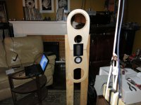
This driver will be used in a 4-way. There will be two Accuton C51 midranges, two Acoustic Elegance TD8M's, two AE PB15H+'s, plus two 18" passive radiators. Massive D'Appolito?
Since the AE's are still months away, I have time to play with the Mundorfs and Accutons.
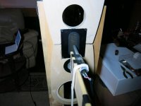
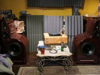
The test baffle is from wood left over, please don't critique?
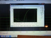
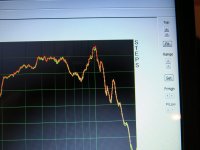
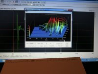
Some preliminary test right out of the box. Near field, 1cm. Low volume. Two 4.7uF safety caps (since these might be close to the final crossover values).
I've never done impulse response/burst decay etc. measurements, so I hope I've done them correctly. If there are any other tests, or changes to tests, please recommend them.
This will be my sixth build, but my first using an AMT (ribbon)? I'm hoping things work out. I'll check out the Planars & Exotics forum for more help.
This driver will be used in a 4-way. There will be two Accuton C51 midranges, two Acoustic Elegance TD8M's, two AE PB15H+'s, plus two 18" passive radiators. Massive D'Appolito?
Since the AE's are still months away, I have time to play with the Mundorfs and Accutons.
The test baffle is from wood left over, please don't critique?
Some preliminary test right out of the box. Near field, 1cm. Low volume. Two 4.7uF safety caps (since these might be close to the final crossover values).
I've never done impulse response/burst decay etc. measurements, so I hope I've done them correctly. If there are any other tests, or changes to tests, please recommend them.
Attachments
-
 IMG_1498.jpg602.1 KB · Views: 625
 -
 IMG_1495.jpg771.8 KB · Views: 591
 -
 IMG_1496.jpg897.1 KB · Views: 559
 -
 IMG_1499.jpg985 KB · Views: 535
 -
 IMG_1500.jpg975.2 KB · Views: 530
 -
 IMG_1501.jpg988.1 KB · Views: 217
 -
 IMG_1502.jpg987.4 KB · Views: 179
 -
 IMG_1503.jpg991.7 KB · Views: 178
 -
 IMG_1504.jpg988.7 KB · Views: 153
 -
 IMG_1507.jpg1,006.5 KB · Views: 172
No, it's not a true ribbon. 🙂
Yes, it's a fantastic driver. 🙂 I'm listening to them now. You really have to use a particle accelerator to damage them, they take tremendous amounts of power.
You should try compression testing. I've done it in the past. Amazing. 🙂
Best,
E
Yes, it's a fantastic driver. 🙂 I'm listening to them now. You really have to use a particle accelerator to damage them, they take tremendous amounts of power.
You should try compression testing. I've done it in the past. Amazing. 🙂
Best,
E
Also, see if you find anything useful here:
SNR-1 : Mundorf / Scanspeak 2 Way
I'm particularly happy of being able to get the tweet flat past 20 kHz.
SNR-1 : Mundorf / Scanspeak 2 Way
I'm particularly happy of being able to get the tweet flat past 20 kHz.
Hi Billy,
Compression just means, is the FR the same at 70 dB as at 90 dB. 🙂
In this review, they call it "deviation from linearity"
SoundStageNetwork.com | SoundStage.com - NRC Measurements: Totem Acoustic Tribe Tower Loudspeakers
Compression just means, is the FR the same at 70 dB as at 90 dB. 🙂
In this review, they call it "deviation from linearity"
SoundStageNetwork.com | SoundStage.com - NRC Measurements: Totem Acoustic Tribe Tower Loudspeakers
PS - As far as I know there is no set standard for compression/linearity testing, but I go by Sound Stage Network for consistency.
I've been listening to the same pair of speakers now for 4 years. They truly are spectacular. The fact that I'm building another similar pair is testament to my neurosis?
There are two things slightly 'off' with my present speakers:
1)this power compression thing your talking about. As much as I love the Accuton 1" diamond tweeter, at concert hall levels, it runs out of steam. At moderate volumes it is all it's claimed to be. I suspect the single Accuton C50 2" midrange also runs out of steam. Hence the move to a D'Appolito with dual C51's (the newer version of the C50).
2)floor bounce. I have a small dip at 240Hz. This makes the speakers slightly midbase light. I'm hoping dual 8" will solve this problem.
This move to an AMT, which on paper looks good, should solve problem 1. I chose this version because of it's sensitivity. Let's see if i dun good?
Attachments
I've been listening to the same pair of speakers now for 4 years. They truly are spectacular. The fact that I'm building another similar pair is testament to my neurosis?
I'll be happy to take the old ones off your hands to save you a trip to the local tip 😀
I'm curious about the AE PB15H+ drivers.
Are these an unlisted Ported Box version of the SBP 15's ?
What box size and tuning can you get away with?
I've been impressed by the Mundorf AMT's distortion at high SPL since Erik posted his measurements years ago, and your measurements, though at low volume, seem to indicate good performance.
I'm still unsure about directivity-matching to the midrange... Mundorf's graphs stop at 15-degrees vertical off-axis, and I'm not sure I've seen good examples of relatively flat, parallel FR curves from an AMT like you'd see from the controlled directivity of a dome + waveguide.
I suppose I wouldn't know for sure without dutifully measuring and matching in-hand, which would likely sway me toward a high-SPL capable dome (Bliesma 34mm maybe) to avoid the fuss. Drat.
Regarding the AE PB15H+; Simply take a TD15H and use a different cone. One with a dust cap as opposed to a phase plug. All other parameters are identical.
Considering how long the AE drivers are going to take, I'll start taking measurements of the AMT from various angles, and from varying distance.
As for the Bliesma, unfortunately I had already purchased the Mundorf when I became aware of it.
I'll post some more measurements in the morning. They will address the myth/truth about cables on the floor versus raised.
I'll also put a piece of foam around the microphone. I remember reading somewhere that it's important for higher frequencies.
I'd like to make sure my measurements are of the tweeter, and not of other 'issues'.
These are a silly set of measurements. For that I apologize.
These measurements are taken at low volumes, 1cm microphone distance.
Does the microphone cable being on the floor make a difference?.
There are subtle changes, but that could be the furnace turning on or off and affecting my electricity.
I will say one thing; at concert hall level volumes, I do hear a difference in my system. Once I start testing at 1M with higher volumes, I'll do these tests again.
1) cable snaked on the floor
2) cable coiled on the floor
3) cable lifted off the floor
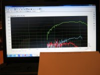
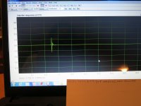
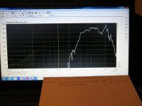
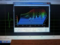
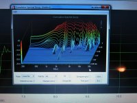
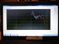
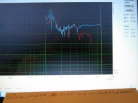
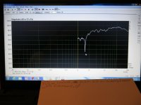
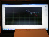
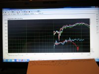
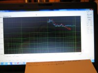
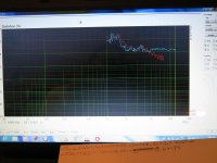
First three picture; frequency response
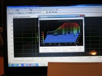
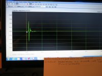
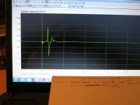
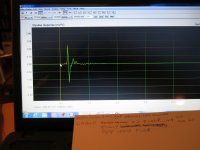
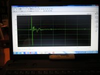
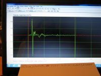
Next three; impulse response
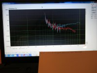
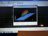
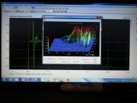
Final three; cumulative decay
Next post; microphone with a foam cover, and without. Microphone in center of AMT, slightly up the face, and then at the top.
These measurements are taken at low volumes, 1cm microphone distance.
Does the microphone cable being on the floor make a difference?.
There are subtle changes, but that could be the furnace turning on or off and affecting my electricity.
I will say one thing; at concert hall level volumes, I do hear a difference in my system. Once I start testing at 1M with higher volumes, I'll do these tests again.
1) cable snaked on the floor
2) cable coiled on the floor
3) cable lifted off the floor
First three picture; frequency response
Next three; impulse response
Final three; cumulative decay
Next post; microphone with a foam cover, and without. Microphone in center of AMT, slightly up the face, and then at the top.
Attachments
-
 IMG_1517.jpg731.8 KB · Views: 314
 -
 IMG_1523.jpg1 MB · Views: 298
 -
 IMG_1526.jpg1,021.5 KB · Views: 277
 -
 IMG_1518.jpg800.9 KB · Views: 283
 -
 IMG_1524.jpg962.3 KB · Views: 272
 -
 IMG_1528.jpg827.3 KB · Views: 87
 -
 IMG_1519.jpg995.8 KB · Views: 90
 -
 IMG_1525.jpg1,010.4 KB · Views: 85
 -
 IMG_1529.jpg1 MB · Views: 86
I understand that you put the mike at 1 cm from the driver. I suggest you at least 50 cm from the front plate and use gating to have proper measurements.
I'll take your advice. Testing this morning will be at 50cm.
I'm not very tech savvy. How do I implement 'gating' in Arta?
I'm not very tech savvy. How do I implement 'gating' in Arta?
We are now at 50cm. 2 x 4.7uF safeties. Louder, but not full 1W.
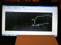
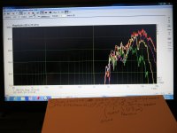
1) frequency response, no foam on microphone head
2) FR with foam on head. The light green trace is the new measurement
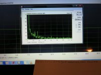
3) distortion, no foam
4) distortion, with foam
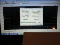
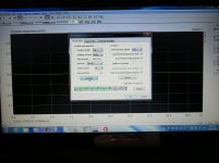
5) impulse response dialogue box. Are the values correct?
6) imp. res.
7) gates on imp. res.
8) cumulative spectral decay. Hmmmm? is this good?
9) imp. res. with foam on the microphone head
10) CSD with foam
1) frequency response, no foam on microphone head
2) FR with foam on head. The light green trace is the new measurement
3) distortion, no foam
4) distortion, with foam
5) impulse response dialogue box. Are the values correct?
6) imp. res.
7) gates on imp. res.
8) cumulative spectral decay. Hmmmm? is this good?
9) imp. res. with foam on the microphone head
10) CSD with foam
Attachments
-
 IMG_1546.jpg832.6 KB · Views: 100
 -
 IMG_1547.jpg985.2 KB · Views: 111
 -
 IMG_1538.jpg906.2 KB · Views: 95
 -
 IMG_1548.jpg987.5 KB · Views: 78
 -
 IMG_1539.jpg978.6 KB · Views: 83
 -
 IMG_1540.jpg661.1 KB · Views: 71
 -
 IMG_1543.jpg794.1 KB · Views: 76
 -
 IMG_1542.jpg992.8 KB · Views: 108
 -
 IMG_1549.jpg896.6 KB · Views: 83
 -
 IMG_1551.jpg995.6 KB · Views: 86
Before I do 'axis' measurements, let's see if my make shift baffle is a problem?
1) picture of the baffle
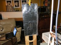
2) picture of the baffle with Sorbothane now covering it
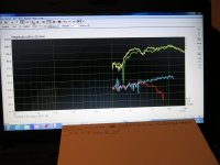
3) overlay a new FR onto this mornings measurements
4) sorbothane measurement by itself
5) new lower distortion measurement with sorbothane attached
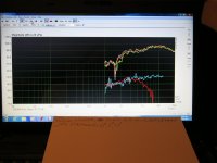
6) 5 degree off axis
7) 10 deg.
8) 15 deg.
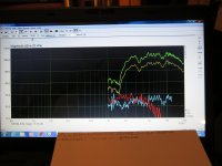
9) reduce the range significantly. We can now see more space. 0, 5, 15, 25, 35 degrees
That's it for today, my wife is looking at me funny?
1) picture of the baffle
2) picture of the baffle with Sorbothane now covering it
3) overlay a new FR onto this mornings measurements
4) sorbothane measurement by itself
5) new lower distortion measurement with sorbothane attached
6) 5 degree off axis
7) 10 deg.
8) 15 deg.
9) reduce the range significantly. We can now see more space. 0, 5, 15, 25, 35 degrees
That's it for today, my wife is looking at me funny?
Attachments
-
 IMG_1553.jpg733.1 KB · Views: 182
 -
 IMG_1555.jpg803.2 KB · Views: 187
 -
 IMG_1556.jpg873.4 KB · Views: 122
 -
 IMG_1557.jpg951 KB · Views: 91
 -
 IMG_1558.jpg864 KB · Views: 137
 -
 IMG_1559.jpg766.6 KB · Views: 83
 -
 IMG_1560.jpg679.6 KB · Views: 75
 -
 IMG_1562.jpg879.1 KB · Views: 88
 -
 IMG_1565.jpg837.8 KB · Views: 105
Over the years I've read a lot of articles. Love this internet thing.
Tempo Electric did a capacitor shoot-out. The Great Capacitor Shoot-Out
In the article they talk about inner foil and outer foil. They discuss orientation, and which one sounds better. They imply the words on the capacitor indicate where the outer foil is connected. I enjoyed the article, though it's a bit long.
I use tube amplification. Tube amplifiers are current sources. Capacitors are voltage devises. Is there a difference in measurements depending on the capacitors orientation?
I did a quick and dirty test with the Jantzen Superior Z, 4.7uF.
Pictures;
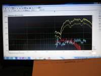
1) A quick frequency response measurement. Lower one at yesterdays volume, plus the new higher volume one. The lime green is always the newest measurement. The Jantzen have their outer foil starting at the speaker. The letters on the cap 'flow' towards the amplifier. I call this 'backwards'.
2) I turned the Jantzens the other way. They are now 'properly?' installed. The lettering flows from the amp to the driver. Please believe me, the test was done. You can't even see the 'new' lime green trace. There is absolutely no difference in frequency response measurements based on cap orientation.
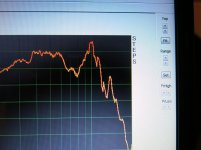
How about distortion?
3) distortion measurement with caps 'backwards'. Zoom in and look closely. Above 5K, D2 does 'not' hit the next line up.
4) caps are now installed properly. Zoom in. Above 5K, D2 hits the next line up. Distortion is higher. However:
We use tube amplification. Tube amplifiers are current sources. Most of you have SS amplifiers, which are voltage sources. Conclusion? if you have a SS amp, install caps properly. If you have a current source, install the caps 'backwards'.
For the scientists out there. One test does not make a conclusion. Time to raise the volume, repeat the test, try different caps.
Tempo Electric did a capacitor shoot-out. The Great Capacitor Shoot-Out
In the article they talk about inner foil and outer foil. They discuss orientation, and which one sounds better. They imply the words on the capacitor indicate where the outer foil is connected. I enjoyed the article, though it's a bit long.
I use tube amplification. Tube amplifiers are current sources. Capacitors are voltage devises. Is there a difference in measurements depending on the capacitors orientation?
I did a quick and dirty test with the Jantzen Superior Z, 4.7uF.
Pictures;
1) A quick frequency response measurement. Lower one at yesterdays volume, plus the new higher volume one. The lime green is always the newest measurement. The Jantzen have their outer foil starting at the speaker. The letters on the cap 'flow' towards the amplifier. I call this 'backwards'.
2) I turned the Jantzens the other way. They are now 'properly?' installed. The lettering flows from the amp to the driver. Please believe me, the test was done. You can't even see the 'new' lime green trace. There is absolutely no difference in frequency response measurements based on cap orientation.
How about distortion?
3) distortion measurement with caps 'backwards'. Zoom in and look closely. Above 5K, D2 does 'not' hit the next line up.
4) caps are now installed properly. Zoom in. Above 5K, D2 hits the next line up. Distortion is higher. However:
We use tube amplification. Tube amplifiers are current sources. Most of you have SS amplifiers, which are voltage sources. Conclusion? if you have a SS amp, install caps properly. If you have a current source, install the caps 'backwards'.
For the scientists out there. One test does not make a conclusion. Time to raise the volume, repeat the test, try different caps.
Attachments
Once you've built your actual speaker, try out the Audyn TC 0.1uF as a bypass cap to anything over 5 uF. 🙂
Conclusion? if you have a SS amp, install caps properly. If you have a current source, install the caps 'backwards'.
Of course, the alternate explanation is you are actually measuring cap break-in. Would be interesting to know if this changes back. 🙂
Best,
E
- Home
- Loudspeakers
- Multi-Way
- Mundorf AMT 25CS2.1-R