I really could not find anything really useful.
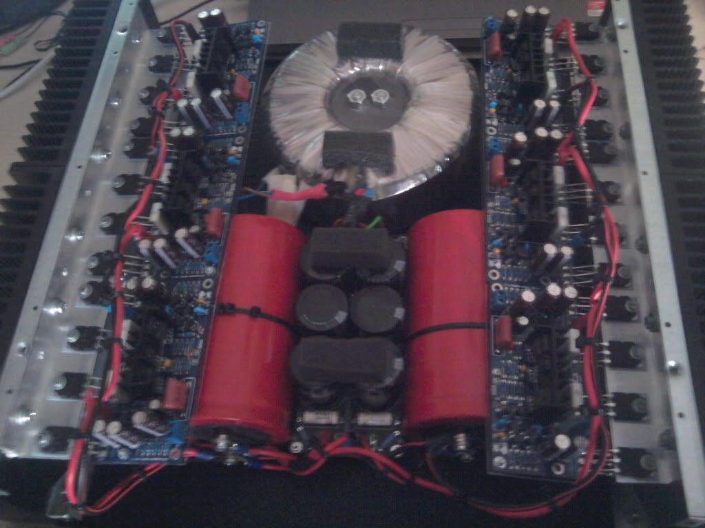
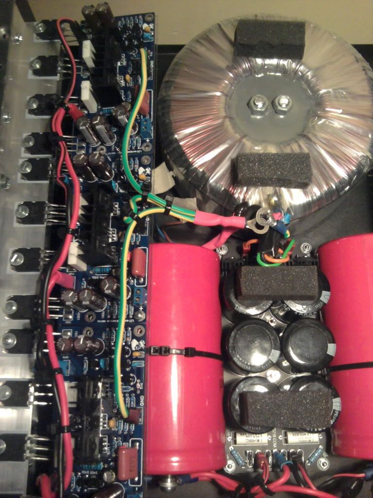
Here is my build:
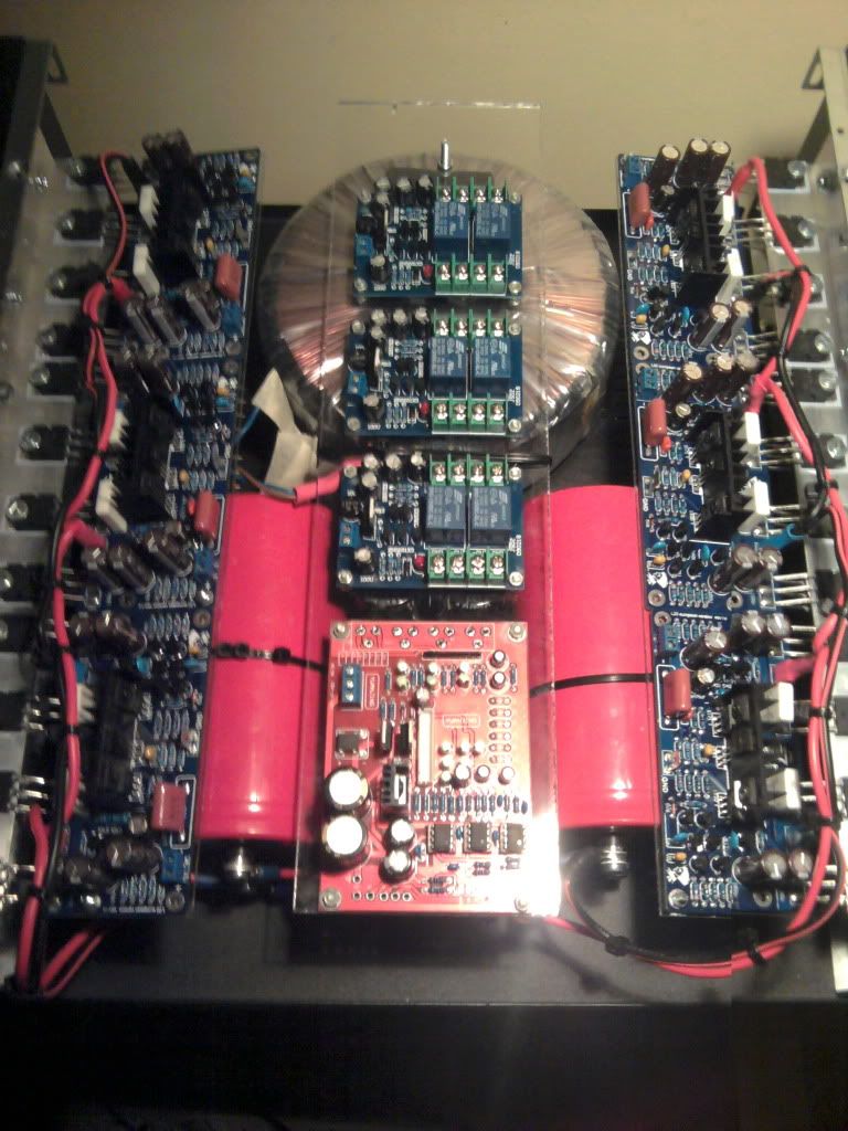
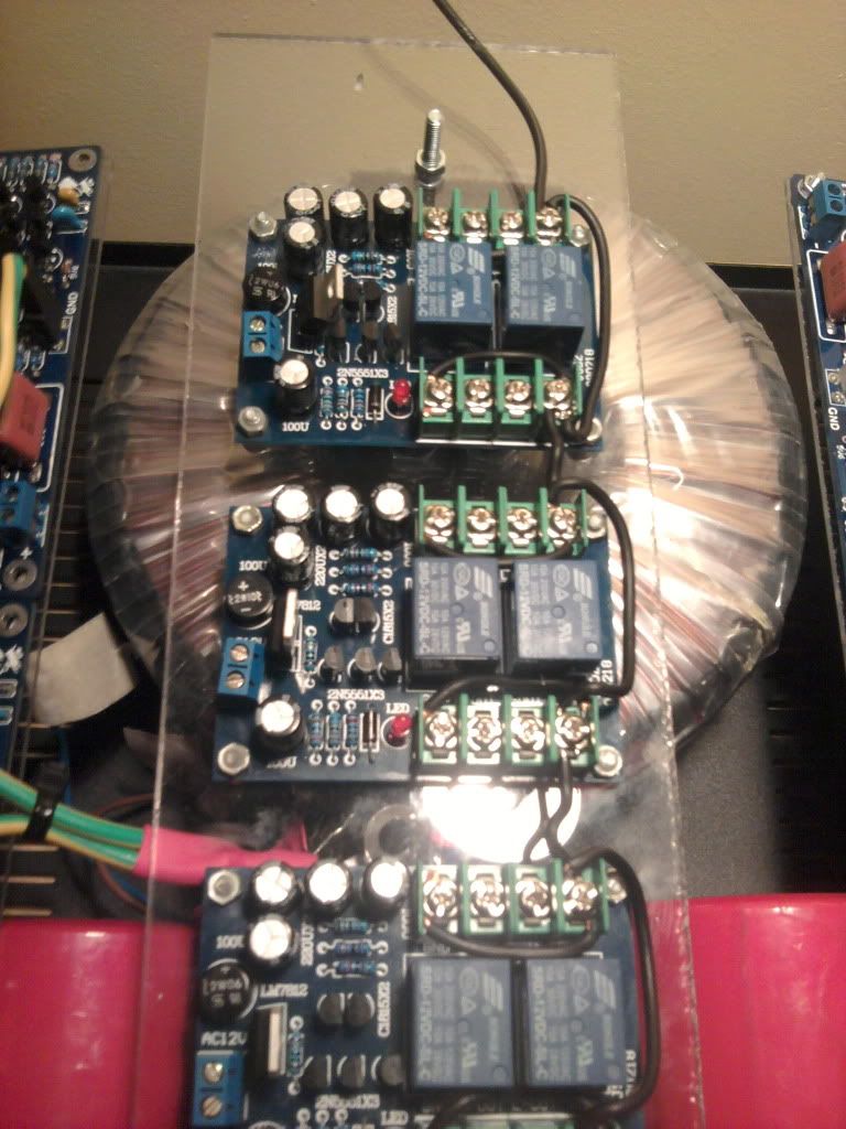
and here is the top layer (dc protect and preamp)
All the amps have a ground faston. I usually wire the output from there to the DC protect modules and over to the speaker output connectors. From there I wire the outputs directly to a central ground.
I understand my approach is totally worng, but what should I do?
Thinking of best ground I imagined 2 ground star centers. One for the power amps and one from the preamp which then merge at the socket ground.
Is this correct?
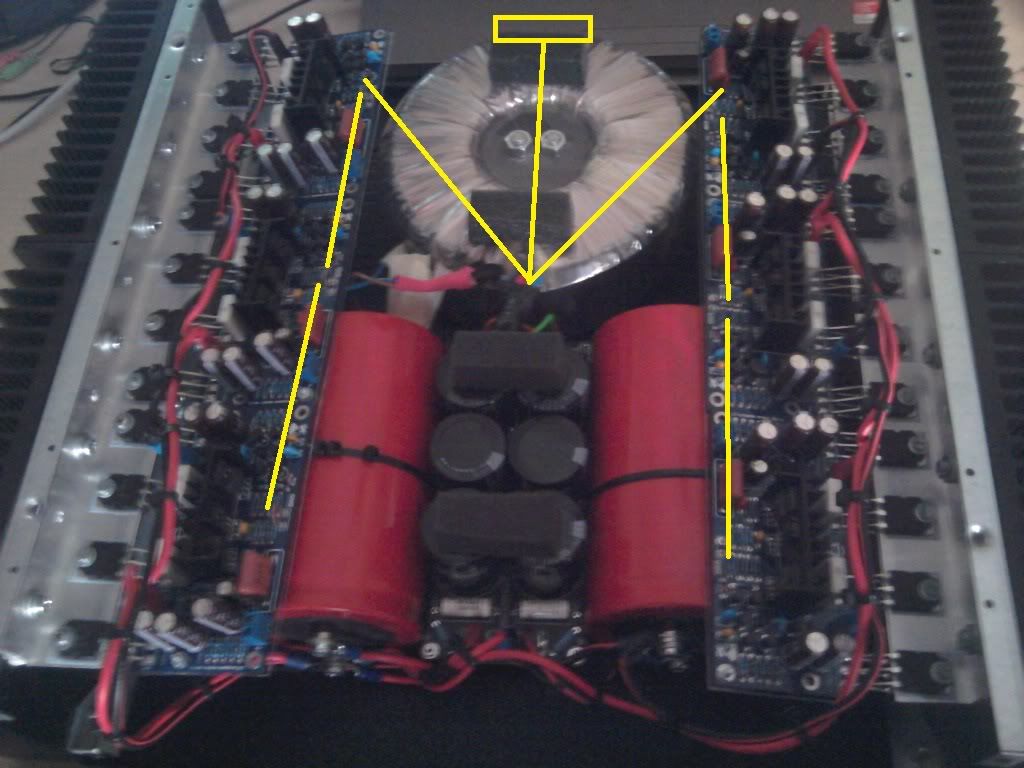
a picture of two alternatives I thought of regarding ground:
1. starground (for the poweramps)

2. non-starground (for the poweramps)
I am really lost....Could someone please sketch with paint over my intial photograph a good design for ground? In the picture with the top layer all the modules are present.
Thanks
Alex
Here is my build:
and here is the top layer (dc protect and preamp)
All the amps have a ground faston. I usually wire the output from there to the DC protect modules and over to the speaker output connectors. From there I wire the outputs directly to a central ground.
I understand my approach is totally worng, but what should I do?
Thinking of best ground I imagined 2 ground star centers. One for the power amps and one from the preamp which then merge at the socket ground.
Is this correct?
a picture of two alternatives I thought of regarding ground:
1. starground (for the poweramps)
2. non-starground (for the poweramps)
I am really lost....Could someone please sketch with paint over my intial photograph a good design for ground? In the picture with the top layer all the modules are present.
Thanks
Alex
Yes the way you did it first was bad. Grounding should be simple and I'm not sure why people get so confused over it.
The master ground reference is at the centre of the big PSU caps. Any boards or loads should have their ground wire back to that point and that point only. The mains ground socket pin should also wire to that point. If your amp boards have a speaker ground terminal, ignore it and wire back to the star point. Unless its a UcD amp.
Input leads to your amp should use screened cable and use the input ground terminal on the board, not back to the star.
Your DC protection module will need a ground just for reference, take this from the star.
Thanks! So star is ok...
couple of other questions:
1. best way to gound black output terminals?
2. Should I connect the preamp ground to another star or connect it directly to the socket AC?
3. chassis is connected to star ground or to socket ground?
couple of other questions:
1. best way to gound black output terminals?
2. Should I connect the preamp ground to another star or connect it directly to the socket AC?
3. chassis is connected to star ground or to socket ground?
"best" is hard to say in multichannel chassis - signal grounds are likely shorted together at the source, preamp card, this makes it hard to avoid loops, common impedance pickup
power gnd distribution shouldn't be considered independent of power distribution as your "star" sketch shows – bundling each amp's pwr gnd return with its own pwr wires reduces radiating loop area
practical "good" is to have gnd loop isolation/breaking in the system - such as differential receivers at the amp boards - sometimes can be done with just a few R tacked on
I would consider reversing/flipping the power caps end for end - where are the rectifiers? - you want the xfmr, pwr diode, pwr reservoir C wiring to be as small in loop area as possible
close packing of all the pieces, planar orientation doesn't help either
Last edited:
Yes the way you did it first was bad. Grounding should be simple and I'm not sure why people get so confused over it.
The master ground reference is at the centre of the big PSU caps. Any boards or loads should have their ground wire back to that point and that point only. The mains ground socket pin should also wire to that point. If your amp boards have a speaker ground terminal, ignore it and wire back to the star point. Unless its a UcD amp.
Input leads to your amp should use screened cable and use the input ground terminal on the board, not back to the star.
Your DC protection module will need a ground just for reference, take this from the star.
I agree with this, I don't even put GND out on my amp boards any more.
"best" is hard to say in multichannel chassis - signal grounds are likely shorted together at the source, preamp card, this makes it hard to avoid loops, common impedance pickup
power gnd distribution shouldn't be considered independent of power distribution as your "star" sketch shows – bundling each amp's pwr gnd return with its own pwr wires reduces radiating loop area
practical "good" is to have gnd loop isolation/breaking in the system - such as differential receivers at the amp boards - sometimes can be done with just a few R tacked on
I would consider reversing/flipping the power caps end for end - where are the rectifiers? - you want the xfmr, pwr diode, pwr reservoir C wiring to be as small in loop area as possible
close packing of all the pieces, planar orientation doesn't help either
the rectifiers are between the black caps and the toroid soldered on the board.
Unfortunately the layout was not a free choice as the space is little and the casings cost a fortune! 🙁
I have also created these:
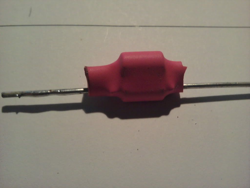
basically two diodes soldered opposite one another with a 100ohm resistor in parallel. Simple ground loop breakers.
Can the be effectively used in my design in critical spots?
Also this is half the ground star design completed:
the connectors will then be wired to the socket ground.
Also the central connector is wired to the caps board underneath.
Here is a picture of the upper layer with the DC modules hooked up to a reference ground wire which will be connected to the socket on the back panel.
I'd like to point out that there's a good article about grounding on diyAudio: http://www.diyaudio.com/forums/diya...udio-component-grounding-interconnection.html. Especially chapter 4 is relevant to this thread.
"best" is hard to say in multichannel chassis - signal grounds are likely shorted together at the source, preamp card, this makes it hard to avoid loops, common impedance pickup
power gnd distribution shouldn't be considered independent of power distribution as your "star" sketch shows – bundling each amp's pwr gnd return with its own pwr wires reduces radiating loop area
practical "good" is to have gnd loop isolation/breaking in the system - such as differential receivers at the amp boards - sometimes can be done with just a few R tacked on
I would consider reversing/flipping the power caps end for end - where are the rectifiers? - you want the xfmr, pwr diode, pwr reservoir C wiring to be as small in loop area as possible
close packing of all the pieces, planar orientation doesn't help either
the rectifiers are between the black caps and the toroid soldered on the board.
Unfortunately the layout was not a free choice as the space is little and the casings cost a fortune! 🙁
I have also created these:
basically two diodes soldered opposite one another with a 100ohm resistor in parallel. Simple ground loop breakers.
Can the be effectively used in my design in critical spots?
Also this is half the ground star design completed:
the connectors will then be wired to the socket ground.
Also the central connector is wired to the caps board underneath.
Here is a picture of the upper layer with the DC modules hooked up to a reference ground wire which will be connected to the socket on the back panel.
you may have to try several of the suggestions to get to "good enough" - measurements are important to keep you moving in the right direction
a even motherboard PC sound chipset should enable measuring gnd impedance signal coupling to ~ -80 dBV
pro instruments, bench multimeters with ACV response to beyond 1kHz, Oscilloscope are pretty necessary
strictly speaking green/yellow should only be used for Protective Earth/Safety Ground - not as functional gnd carrying current in normal operation
inside a amp chassis it would only be used between the IEC socket Earth Ground pin, chassis gnd and the star point
not a big problem if not going to be officially inspected or sold to the unsuspecting
Thanks! So star is ok...
couple of other questions:
1. best way to gound black output terminals?
2. Should I connect the preamp ground to another star or connect it directly to the socket AC?
3. chassis is connected to star ground or to socket ground?
1. I already told you, speaker ground to star.
2. If the pre-amp is in the same box use the star. Do not link grounds between the two boards by the signal cable - the signal cable should either be a single wire connecting signal only, or a screened cable with the screen terminated at only the amp input end.
3. Socket ground should have a short thick wire to the enclosure and be attached to a bare metal point via a shakeproof washer. This bolt should not be used for any other purpose, not even mechanical or electrical. The star should connect to the socket ground.
power distribution, gnding principles may be "simple" - applying them not so
there are several concerns, conflicting "requirements", different possible "solutions"
I don't think it is always a good idea to totally bypass the amp board gnd with the pwr gnd run Only to the star and speaker output connector
compensation, on board HF decoupling wants a very local "gnd" connection in most circuits - "local" to the output Q, load - relying on a run back to the star gnd to have low enough inductance could be asking for trouble
a "T" is a possibility with 2 wires crimped in the board pwr gnd faston - with the extra wire continuing to the output connector (twisted with the amp +output wire)
but depending on board layout you shouldn't "have to" go around the existing pwr, output connectors
and again, if you want to approach the "best" in the thread title, the star pwr gnd wire should be bundled/twisted with the pwr wire pair for each board individually
input signal gnd can be another story though - depending on your requirements for channel isolation and preamp/distribution board's circuit details - add DRV134 to each channel?
Last edited:
Re: 2, don't forget the option of using insulated jacks and a cable with connected shield at both ends. That way the shield can't carry any earth current.1. I already told you, speaker ground to star.
2. If the pre-amp is in the same box use the star. Do not link grounds between the two boards by the signal cable - the signal cable should either be a single wire connecting signal only, or a screened cable with the screen terminated at only the amp input end.
3. Socket ground should have a short thick wire to the enclosure and be attached to a bare metal point via a shakeproof washer. This bolt should not be used for any other purpose, not even mechanical or electrical. The star should connect to the socket ground.
This issue caused me a significant headache trying to understand why there were all these "rules" as to what to do, and what not to do. It started to make a lot more sense when I realized that you have to create a point in the amp that is at the same and constant potential. It is usually chosen as the center tap on the transformer secondary. Next in all the various ground wires you will have a current flow. If there is current flow, then all points along the wire will have a different potential, even though it is essentially "ground". The higher the current flow the larger the potential differences. I found it helpful to map out all the major current flows in the amp -- such as the PS capacitors, the speaker load, and the "board" loads. As far as possible you want to keep those current loops separated, and the ground part going independently back to the chosen reference point (commonly called the star point). Where you have used a twisted pair for signal shielding you want to route the wire as much as is possible so the current in the two wires is equal and opposite.
Once you get your head around that, then the grounding scheme (at least to me) starts to make a lot more sense. The key point is current flow mapping.
Once you get your head around that, then the grounding scheme (at least to me) starts to make a lot more sense. The key point is current flow mapping.
Yes. Treat every wire, however short, as a resistor and ask what current it will be carrying and so what voltage will be developed across it. Ask what varying magnetic field will be developed by every circuit loop. Ask what varying magnetic field will be seen by every other circuit loop. Doing it this way means that you can design a grounding scheme, rather than blindly following a set of rules.
In parallel with this, think about safety. What will happen if live mains touches something metallic, which your wife/child happens to be touching at the same time?
In parallel with this, think about safety. What will happen if live mains touches something metallic, which your wife/child happens to be touching at the same time?
the transformer, rectifier, smoothing caps wiring route passes high current pulses. This must be in a very tight loop. Do not let any audio cable share any part of any of the PSU loop route.jcx; said:I would consider reversing/flipping the power caps end for end - where are the rectifiers? - you want the xfmr, pwr diode, pwr reservoir C wiring to be as small in loop area as possible
A single point from the PSU Zero Volts should be taken to the Main Audio Ground (MAG). DO NOT locate the MAG in the PSU loop.
this is important and often missed.............I don't think it is always a good idea to totally bypass the amp board gnd with the pwr gnd run Only to the star and speaker output connector
compensation, on board HF decoupling wants a very local "gnd" connection in most circuits - "local" to the output Q, load - relying on a run back to the star gnd to have low enough inductance could be asking for trouble
The onboard decoupling must be in a very short tight loop with the output Trs and PWR GND.
The on board Zobel R+C must be in a very tight loop with the output Trs and the PWR GND
These two loops only pass very high frequency transients. Inductance must be avoided at all costs.
JCX is correct. Read carefully, if any part confuses you then ask for clarification.
Last edited:
Thanks all for your precious help. I've had a look at the article and read our posts very carefully. Please excuse me for mistakes but this is a difficult subject for me.
The diodes/caps board is one and therefore I cannot flip the large red caps without lengthening the connectin wires. The transformer outputs, cap boad inputs and first star ground connction are very close. The closest possibile route. The 220v run in thick shielded cable to the softsart (under the modules) and over to the transformer. Figure a "cross" like configuration with cap board, transformer, softstart and secondary toroidal.
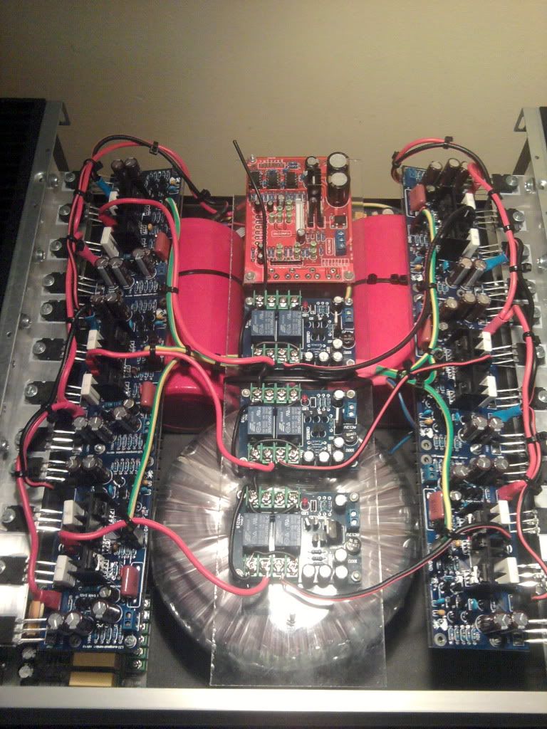
Here is a pic:
Since I am not going to sell this amp the colours choseen are random and/or help me keep my bearing.
The pwr cables rung vertically in the pic. A single star poiint (under the plexi) connects both amps AND ground powersupply. I cable takes the star back to the rear panel for socket connection.
Outputs from the amp go directly to the DC protect modules. GND for the modules is kept as small as possibile and is independent. It connects directly the rear panel (with the black wire at the back of the plexi strip).
Ther preamp will have its own ground and be wired directyl to the socket earth.
the output terminal will be star connected (all 6 outputs only) and from there connected to socket ground.
I tried to keep all stages separate and the wiring as short as possibile. Casing will obviously be connected directly to the socket ground via a dedicated small but thick cable.
What do you guys think?
I also rigged my pc to take readings through my soundcard. I guess some very limited testing can be done..
I also gather that only real sound tests are conclusive since this was not planned by an engineer and mistake are bound to pop up.
The diodes/caps board is one and therefore I cannot flip the large red caps without lengthening the connectin wires. The transformer outputs, cap boad inputs and first star ground connction are very close. The closest possibile route. The 220v run in thick shielded cable to the softsart (under the modules) and over to the transformer. Figure a "cross" like configuration with cap board, transformer, softstart and secondary toroidal.
Here is a pic:
Since I am not going to sell this amp the colours choseen are random and/or help me keep my bearing.
The pwr cables rung vertically in the pic. A single star poiint (under the plexi) connects both amps AND ground powersupply. I cable takes the star back to the rear panel for socket connection.
Outputs from the amp go directly to the DC protect modules. GND for the modules is kept as small as possibile and is independent. It connects directly the rear panel (with the black wire at the back of the plexi strip).
Ther preamp will have its own ground and be wired directyl to the socket earth.
the output terminal will be star connected (all 6 outputs only) and from there connected to socket ground.
I tried to keep all stages separate and the wiring as short as possibile. Casing will obviously be connected directly to the socket ground via a dedicated small but thick cable.
What do you guys think?
I also rigged my pc to take readings through my soundcard. I guess some very limited testing can be done..
I also gather that only real sound tests are conclusive since this was not planned by an engineer and mistake are bound to pop up.
Selling a self built amplifier for which you have little to no knowledge of Safety Issues is bordering on the irresponsible.
You must test this equipment for all sensible failure modes, to ensure that what you have wired cannot kill the next user/operator.
I will report my own post, no need for anyone else to trouble themselves.
You must test this equipment for all sensible failure modes, to ensure that what you have wired cannot kill the next user/operator.
I will report my own post, no need for anyone else to trouble themselves.
I must study more but you sir must learn to read other posts with more attention before passing sentence.
As in the watercooling thread i sense hostility.
Thankyou everyone for your help. I guess i will solve this on my own.
Inviato dal mio GT-I5800 usando Tapatalk
As in the watercooling thread i sense hostility.
Thankyou everyone for your help. I guess i will solve this on my own.
Inviato dal mio GT-I5800 usando Tapatalk
Who else's posts border on the irresponsible that deserve the Moderators' attention?
watercooling: I tried to explain how to get good cooling with various arrangements. I went on to explain how to go fanless and pumpless. These contributions were all intended to help you to solve your perceived problems.
watercooling: I tried to explain how to get good cooling with various arrangements. I went on to explain how to go fanless and pumpless. These contributions were all intended to help you to solve your perceived problems.
To err is human to persist is not... Read back the first.sentence of the post you believed to be irresponsible. See the "not"? It.is there for a very good reason. I do not plan on selling the amp.
Inviato dal mio GT-I5800 usando Tapatalk
Inviato dal mio GT-I5800 usando Tapatalk
- Status
- Not open for further replies.
- Home
- Amplifiers
- Solid State
- Multiple components. Best ground design?