HI!
In my mixer design i mult the main output to have a monitor output, so one signal goes to the recorder and the other to an external monitor controller. ok so far.
THE QUESTION IS:
1.As there are two connectors linked in parallel..
¿should i put RFI filters ON BOTH CONNECTORS? ¿¿or just the first one??
I profit the occasion to make another question that worried me a bit...
2.Some connections between my opamp (dip8) stages are made with long traces (15 to 25cm long 0.8mm wide) on the top layer over a free ground plane in the bottom layer, because the audio connectors are spread all on the edge of the board, and the opamp stages are near each connector.
¿50 or75 R output isolator resistor is enough? or should i place an RFi T filter on the opamp outputs? (analog devices MT-096)
Tha bandwidth of my opamp stages varies between 140khz (summing amplifier) to 300khz aprox ( balanced transformer driver with low feedback resistors 1k or 2k2)
Some details of my RFI protection:
My plan is to use RFI filters as per the THAT schematics 1246 rfi input 47pf to chassis /470pf/470pf smd 1206.And for the outputs murata BLO2 series 140R @100mhz ferrites with 100pf. All connectors with metal shell or metal threaded nose in case of jacks, so there is a direct connection to metal case.
Besides, all the pcb area of the connectors is separated from the audio common.(by thin cutout rectangles)...but it is a bit difficult to realize...😀
Thank you for your advise!!
Jay x
Hi!
Well, after looking for info around the web, i think it is necessary to protect every audio connector against RFi. This means placing filters or ferrites on every connector. Apart proper grounding techniques Pin 1 to chassis etc...
Some weeks ago i made a little test with an old sound module AKAI Sg01v,
I connected a 1/4 mono jack to the output, and the other side to a KRK v6 speaker. I run the demo songs, while surfing the net with my mobile placed over the cover of the sound module... not a single click... no burping... nothing..I opened it, and found many 1/8w resitors, axial caps (for hybrid grounding), and the audio connectors (with metal nose) with direct contact to chassis.... no RFI filters, of any kind....
A bit confusing....
Jay x
I would recommend RF filters as near to each connector (so two filters) as near as possible. You want to filter any RF as near to the entry (or exit) point as possible. Some bespoke connectors will have the filtering built in, though I don't know whether you can get XLR with them built in, worth looking for. The whole point of RF is to keep it out, once its in... its a big problem, the perfect solution is shunting it at point of entry to the chassis.
Point 2 are you running the lines over a ground plane?
Low level analogue in my opinion and my experience should have a contiguous ground plane, not a popular view in the domestic audio world but used in all other areas of analogue design including pro stuff.... though there are tricks such as balanced routing (a must for balanced signals, but can also be used with single ended signals) that can be used, the choice is dependant on the circuit and the layout. Any extra info would help.
Two excellent links...
http://www.hottconsultants.com/pdf_files/aes-2007.pdf
http://www.hottconsultants.com/pdf_files/Audio Interconnections.pdf
Last edited:
Hi Marce!
Yes!, all my line are over a continous UNCUT ground plane, so for every line on the top layer, there is ground in the bottom layer...even if this means that i had to place wire jumpers on the top layer...
Yes!, all my line are over a continous UNCUT ground plane, so for every line on the top layer, there is ground in the bottom layer...even if this means that i had to place wire jumpers on the top layer...
Hi Marce!
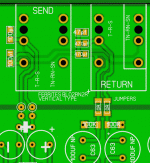
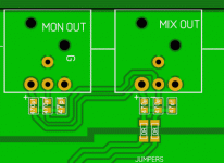
Attached is my PCB layout of the rfi protection of send/return connectors and XLR output connectors.
The connectors ground is separated from the audio ground plane by the horizontal cut out traces.
For the half normalled send return circuit i could not avoid placing two traces on the bottom layer of the chassis ground...
The rfi capacitors are 1206 or 0805 size. Those who are connected to chassis ground are connected by a trace on the top layer, not a thermal pad.
Apart of this i would like to know if the RFi layout is ok... and if the 0 ohm jumpers can be replaced by ferrites.. or it is not necessary..
Thank you very much!
Attachments
NC3MXX-EMC - Neutrik
Seem to have dropped from £16 to £9 each recently. At under a tenner possibly worth it for piece of mind.
Seem to have dropped from £16 to £9 each recently. At under a tenner possibly worth it for piece of mind.
- Status
- Not open for further replies.
- Home
- Design & Build
- Construction Tips
- Multing balanced line outputs RFI protection

