Dear All:
I have seen several multiloop amp configuration where there is a 100 ohm resistor between the op amp and the buffer.
I would like to know if the output impedance will be 100 ohm or it will be the buffer output impedance?
I know that the buf634 output impedance is 10 ohm aprox.
I'm including the Pimenta V2 link with the schematic with this configuration:
http://tangentsoft.net/audio/pimeta2/misc/sch-2.01.pdf
A 100 ohm resistor between the buffer and op amp will have no bearing on output impedance, regardless of feedback configuration. It is an anti-parasitic scheme, intended to isolate the output stage of the op amp from induced signals being introduced into the op amp. And it works; and it is a good idea.
If I have a long circuit board trace between the op amp and buffer, I split the resistor (47+ 47 ohm) and put one resistor right on the op amp output, and the other resistor right on the buffer input. This effectively isolates both parts of the amplifier from induced signals.
Likewise the 10 ohm output impedance of the 634 will be greatly reduced by the global feedback. If your circuit uses large loop gain (heavy feedback) it will be significantly under 1 ohm.
Member
Joined 2009
Paid Member
I always thought that you take the output impedance of the final drive to the speaker (aka the buffer) and divide it by the feedback factor. Say the buffer has a 10R output impedance without feedback, then you apply 20dB of feedback so you get 10R / factor of 10 which gives you a 1R output impedance ?
Do I have to connect the OPA634 BandWidth Pin to v- to achieve better stability when using an opa2134 or OPA627?
I have seen a resistor between the OPA634 bandwidth pin and B-.
Regards.
Alfredo Mendiola loyola
Lima, Peru
I have seen a resistor between the OPA634 bandwidth pin and B-.
Regards.
Alfredo Mendiola loyola
Lima, Peru
R7 could be replaced with a Zobel instead with similar aid to stability
its not really isolating the buf634 input C but rather damping any squirrely Z from the buf634's 100% internal feedback that can give a region of negative input Z way above the op amp GBW
you can look up EF negative input Z and base stopper - which can also sometimes be functionally replaced with Zobel to gnd (or collector/drain rail for a shorter loop)
What is the purpose of the connection named (PREBUF Left/Right) on the Pimenta V2 Schematic?
I have seen transistor/mosfets on that connection....
http://tangentsoft.net/audio/pimeta2/misc/sch-2.01.pdf
Regards.
Alfredo Mendiola Loyola
Lima, Peru
I have seen transistor/mosfets on that connection....
http://tangentsoft.net/audio/pimeta2/misc/sch-2.01.pdf
Regards.
Alfredo Mendiola Loyola
Lima, Peru
What is the purpose of the transistors on the right or left prebuffer?connects to other page of schematic - to the ccs on the Power Supply page
Looks like attempt to bias output stage of opamp to what people call "SE class A", but benefits seem doubtful since opamp if drives rather high impedance load anyway.
Last edited:
Can I replace the Pot from 50K to 10k, Remove R1 and change R2 from 499K
to 100K like the cmoy input stage?
Schematic:
http://tangentsoft.net/audio/pimeta2/misc/sch-2.01.pdf
Regards
Alfredo Mendiola Loyola
Lima, Peru
to 100K like the cmoy input stage?
Schematic:
http://tangentsoft.net/audio/pimeta2/misc/sch-2.01.pdf
Regards
Alfredo Mendiola Loyola
Lima, Peru
I guess no harm in going to 10k pot as far as your signal source is happy with that.
Changing R2 to 100k is possible, but it will affect your lower cut off frequency. You can increase proportionally C1 to keep it similar.
Not sure what was the exact purpose of R1 in this case. May be some sort of protection of opamp input in case of heavy input overload. See first of all if this sort of situation possible in your case.
I believe R1 is a ill thought out attempt to even up source Z to the op amp +,- inputs
clearly misses the fact the volume pot Z varies by much more
the R5,R6 "inner loop" is also a conceit inspired by Otala's "flat open loop gain over the full audio range" prescription
also a logical fail, doesn't work as intended in this circuit even if Otala was correct - which he wasn't
I quite agree that the ccs pull down is not likely helpful when driving the BUF634 input
Tangent and Headwize did introduce many to DIY, lots of documentation, encouragement, support - but I'm afraid some "cargo cult" design features became popular despite poor EE justification
Last edited:
I believe R1 is a ill thought out attempt to even up source Z to the op amp +,- inputs
clearly misses the fact the volume pot Z varies by much more
Yeah, it was my first though, but then "no, it just doesn't match at all" 🙂
Last edited:
I believe R1 is a ill thought out attempt to even up source Z to the op amp +,- inputs
clearly misses the fact the volume pot Z varies by much more
the R5,R6 "inner loop" is also a conceit inspired by Otala's "flat open loop gain over the full audio range" prescription
also a logical fail, doesn't work as intended in this circuit even if Otala was correct - which he wasn't
I quite agree that the ccs pull down is not likely helpful when driving the BUF634 input
Tangent and Headwize did introduce many to DIY, lots of documentation, encouragement, support - but I'm afraid some "cargo cult" design features became popular despite poor EE justification
The purpose of the inner loop is to reduce the op amp bandwidth to avoid oscillations.
Regards.
Alfredo Mendiola Loyola
Lima, Peru
It is true for C6 but not for R6.
Strictly speaking, R6 even increases the bandwidth, proportionality lowering the gain 😀
Strictly speaking, R6 even increases the bandwidth, proportionality lowering the gain 😀
Last edited:
It is true for C6 but not for R6.
Strictly speaking, R6 even increases the bandwidth, proportionality lowering the gain 😀
The Inner Loop gives a gain of 10v/v gain = 20dB, this give a bandwidth of 1Mhz with the opa2134.
The capacitor C6 reduces the bandwidth to 60 khz aprox.
Regards.
Alfredo Mendiola Loyola
Lima, Peru
Last edited:
It is roughly correct, except that I see a different gain. Rather 26dB, or round about it.
Don't forget about the difference between a bandwidth and a gain-bandwidth. While they are related, they are not the same 🙂
Added:
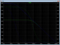
Here is example how R6 affects loop gain stepping from 1e8 Ohm to 499kOhm. Used voltage sources instead of opamap.
Don't forget about the difference between a bandwidth and a gain-bandwidth. While they are related, they are not the same 🙂
Added:
Here is example how R6 affects loop gain stepping from 1e8 Ohm to 499kOhm. Used voltage sources instead of opamap.
Attachments
Last edited:
I have seen several multiloop amp configuration where there is a 100 ohm resistor between the op amp and the buffer.
Curious about this and just did some datasheet diving. 🙂 Along with the other reasons there is an internal diode clamp of about 3V from input to output in the buf634. Turns out the LME49600 has exactly the same thing. I've missed that about both chips.
If for some reason the buffer output can't follow the input - which could happen with op-amp drive if someone doesn't get a solder joint right on a DIY build - the buffer input will conduct hard. Both buffer chips have an internal 200R input resistor to help mitigate the current flow, but if the rails are 12Vdc and the drive op-amp shoots up to the rail due to a broken feedback loop, that would be 12V/200R = 60mA, enough to possibly fry the op-amp's output stage if the op-amp is one without short circuit protection.
Looks like having a "safety" 750R-or-so resistor in series with the buffer input might not be a bad idea. That would limit build accidents to 16mA on the op amp output. I don't see any spec for the input capacitance on either the buf634 or LME49600 datasheets, but guessing 100pF that would put the corner freq of the filter formed at 1.5MHz, way out of audio range, so it shouldn't matter.
Last edited:
- Status
- Not open for further replies.
- Home
- Amplifiers
- Headphone Systems
- MultiLoop Amp Output impedance