Hi all,
I'm building a pc based media system with software digital crossover. I plan to use one of the diyinhk USB xmos boards that can provide multi channel i2s output. I have become confused though by the many options available and potential pitfalls.
I require 2 stereo channels, so in theory it seems i should be able to connect 2 stereo i2s DACs to one xmos board, using the same clock lines for both but different data lines from the xmos board. That is fine for simple DACs, but for the more complex ones such as those based on the AK4399 or PCM1794A, an i2c connection also seems to be required. hiyinhk actually have two AK4399 boards, and one of them has room for jumpers, so can presumably be controlled manually, but then would i have to change the jumper setting for every change in sample rate? rolling my own firmware for the xmos is not an option unfortunately.
Unfortunately their 8 channel dac board is too large to fit in the space available.
suggestions welcome 😉
maybe this is an solution for you too:
http://www.diyaudio.com/forums/soft...e-7-1-av-receiver-over-display-port-hdmi.html
Regards
Guenter
http://www.diyaudio.com/forums/soft...e-7-1-av-receiver-over-display-port-hdmi.html
Regards
Guenter
Hi all,
I'm building a pc based media system with software digital crossover. I plan to use one of the diyinhk USB xmos boards that can provide multi channel i2s output. I have become confused though by the many options available and potential pitfalls.
I require 2 stereo channels, so in theory it seems i should be able to connect 2 stereo i2s DACs to one xmos board, using the same clock lines for both but different data lines from the xmos board. That is fine for simple DACs, but for the more complex ones such as those based on the AK4399 or PCM1794A, an i2c connection also seems to be required. hiyinhk actually have two AK4399 boards, and one of them has room for jumpers, so can presumably be controlled manually, but then would i have to change the jumper setting for every change in sample rate? rolling my own firmware for the xmos is not an option unfortunately.
Unfortunately their 8 channel dac board is too large to fit in the space available.
suggestions welcome 😉
You can use to stereo dac's to give you 4 channel output, they really do need to be the same to keep the differences between them as small as possible.
You will be using i2s to connect the dac's if you use the multichannel diyinhk board. The clocks lines will be wired to the same point on usb card and the data channels taken to the appropriate dac's.
If you do this keep the wiring as short as possible and use one ground wire for each connection if possible to give the shortest return path. Like this

Even though the other DAC boards are smaller remember that you will need power supplies and the power supplies are usually way bigger than the DAC board so take that into consideration for space restrictions. Look at the size of the dac board in comparison to the power supply in this dac of mine.

I have the multichannel diyinhk board with ES9016 DAC and I am yet to work out a good method for sample rate changes as the driver itself needs to be set to a particular rate.
To be honest I think that the better solution would be a 4 channel pro usb soundcard from focusrite or similar. They are very good and will do all you need in the one box.
Thanks fluid, that helps. I hadn't realized that about the driver. This will be a linux based system though so i wonder if that still applies? i think the linux driver is the one that comes with the kernel so i had assumed it will just work like any other sound card. If the worse comes to it i could resample everything to 192/24 thought that is sub-optimal if the original source is some oddball sample rate like 48kHz
I did actually get a multi channel sound card (asus zonar 5.1) but its too big, i didn't much care for the dac chip and it had unnecessary frills like a volume knob and buttons that made me a bit leery about burying it in the middle if this very densely packed chassis in case it randomly decides one of them needs to be pressed before it will work.
I was planning to use bog standard lm317 based power supplys at least to start with and see how it goes. I have 10cm*10cm*9cm to play with so can stack boards if necessary.
Thanks fluid, that helps. I hadn't realized that about the driver. This will be a linux based system though so i wonder if that still applies? i think the linux driver is the one that comes with the kernel so i had assumed it will just work like any other sound card. If the worse comes to it i could resample everything to 192/24 thought that is sub-optimal if the original source is some oddball sample rate like 48kHz
I did actually get a multi channel sound card (asus zonar 5.1) but its too big, i didn't much care for the dac chip and it had unnecessary frills like a volume knob and buttons that made me a bit leery about burying it in the middle if this very densely packed chassis in case it randomly decides one of them needs to be pressed before it will work.
I was planning to use bog standard lm317 based power supplys at least to start with and see how it goes. I have 10cm*10cm*9cm to play with so can stack boards if necessary.
Driver was probably the wrong word to use, I tested it with MacOS so no driver as such. The device is UAC compliant so Linux or Mac can address it directly. You do need to select a sample rate in the control panel. If all your music is the same rate there is no issue. It will work if there is a mismatch between 44.1 and 48 but you will get ringing in the impulse response from the sample rate mismatch.
The simple solution is as you say to set the card at 192 and have the software player upsample to that if necessary.
I did set it to 192 and try with itunes but I can't remember if it actually played or not as itunes is not upsampling. I will have to plug it back in and try.
The multichannel xmos board is quite power hungry so if using linear regs you will need to keep the input voltage close to the required output voltage or you will be generating a lot of heat, not ideal for stacking.
It is often the transformers that take up the space, where are you getting your input voltage from?
The xmos needs 3.3V, and a DAC will need 3.3V and +/-12V or similar for the opamp output stage depending on which board you get.
I don't really understand why the external soundcard needs to be inside a chassis? Maybe a picture would help.
ok, i should have been more specific about the power supply's, the *analog* supplies will be linear lm317, the digital ones will be switching.
Pics!
here we see a view from what will be the rear. in the forground you have 4 modified ESP101 mosfet amp PCBs, two speaker protection relays and the source stack which comprises an intel NUX motherboard at the base, and some unpopulated pcbs above it. the stack will have regulators, an arduino to tie everything together, speaker protection circuitry, usb interface, DACs and finally at the top a motion feedback PCB. in the background you have the smoothing caps and power supply section. the two transformers on top are for analog and digital supplies, the power transformer for the amps is under them and only just visible.

another view form the top

as you can see it's quite cramped and what free space there is will probably be taken up with wiring.
Pics!
here we see a view from what will be the rear. in the forground you have 4 modified ESP101 mosfet amp PCBs, two speaker protection relays and the source stack which comprises an intel NUX motherboard at the base, and some unpopulated pcbs above it. the stack will have regulators, an arduino to tie everything together, speaker protection circuitry, usb interface, DACs and finally at the top a motion feedback PCB. in the background you have the smoothing caps and power supply section. the two transformers on top are for analog and digital supplies, the power transformer for the amps is under them and only just visible.
another view form the top
as you can see it's quite cramped and what free space there is will probably be taken up with wiring.
as you can see it's quite cramped and what free space there is will probably be taken up with wiring.
That is a bit of an understatement!
The simple option is to put your external audio interface on the top of the chassis and cut holes for your USB port and audio input signal connectors on the back panel.
There are a few options for DAC's I could suggest.
The Curryman DAC's are quite nice and stack well as they use headers for the clock and data. Most of the regulators are on board so you just need to supply +/-15 for the buffer and 5 to 12 for the DAC. Minidsp also has an 8 channel USB interface similar to the diyinhk one.
https://www.minidsp.com/products/minidspkits/curryman-i2s-dac
The diyinhk es9010k2m dac's are quite small and would be easy enough to stack as well use a solid pin between the clock points you want to bridge. They need 3.3V x 2 and +/-12V they sound good to me.
Diyinhk also has an ES9023 board that will only need 5V, cheap but still a pretty good chip.
For regulators consider using LT3080 regulators instead of 317. They have lower dropout and do not get as hot. Voltage is set with one resistor and they don't need as many capacitors to perform well. A variable regulator can be built virtually point to point on the pins. They do need a minimum load so use an LED. They are more expensive though.
If you have dual secondaries on your transformer you can use two positive regulators to get the bipolar supply. If not you would need to use positive and negative regulators and split the rail, use a voltage doubler or some sort of switching chip.
Consider isolation of the DAC's as with them connected to usb with an arduino and all that other stuff you are very likely to get ground loop issues unless you use some galvanic isolation somewhere.
You can use to stereo dac's to give you 4 channel output, they really do need to be the same to keep the differences between them as small as possible.
You will be using i2s to connect the dac's if you use the multichannel diyinhk board. The clocks lines will be wired to the same point on usb card and the data channels taken to the appropriate dac's.
If you do this keep the wiring as short as possible and use one ground wire for each connection if possible to give the shortest return path. Like this
View attachment 596064
Even though the other DAC boards are smaller remember that you will need power supplies and the power supplies are usually way bigger than the DAC board so take that into consideration for space restrictions. Look at the size of the dac board in comparison to the power supply in this dac of mine.
View attachment 596063
I have the multichannel diyinhk board with ES9016 DAC and I am yet to work out a good method for sample rate changes as the driver itself needs to be set to a particular rate.
To be honest I think that the better solution would be a 4 channel pro usb soundcard from focusrite or similar. They are very good and will do all you need in the one box.
I see that you are running the DIYINHK usb in multichannel mode and I hope that
you can verify the I2s connections for me. I did a "paint job" that looks like this.
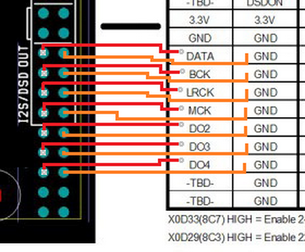
The driver/mixer gives me 6 channels of output in both win7 and win10 but I haven't connected it to anything yet.

I see that you are running the DIYINHK usb in multichannel mode and I hope that
you can verify the I2s connections for me. I did a "paint job" that looks like this.
The driver/mixer gives me 6 channels of output in both win7 and win10 but I haven't connected it to anything yet.
Yes that is right, matches the legend on the back of the board that I have.
Be aware that there are different versions with different firmwares so the pinouts could be different. Diyinhk could not tell me which pins were used for the sample rate indications.
I have only used it with macOS and that gave me 10 channel from memory, it definitely had the full 8 channels that the ES9016 could use. I tested that.
It is possible that you have a different firmware as there are some that only have six channels at a higher sample rate. Mine is 192KHz max.
What version of firmware do you have?Yes that is right, matches the legend on the back of the board that I have.
Be aware that there are different versions with different firmwares so the pinouts could be different. Diyinhk could not tell me which pins were used for the sample rate indications.
I have only used it with macOS and that gave me 10 channel from memory, it definitely had the full 8 channels that the ES9016 could use. I tested that.
It is possible that you have a different firmware as there are some that only have six channels at a higher sample rate. Mine is 192KHz max.
I have v21.02 and in this firmware 8 channels to the input and 8 to the output.
What version of firmware do you have?
I have v21.02 and in this firmware 8 channels to the input and 8 to the output.
I don't know which number it is, there are the 8 channels of i2s but also 2 channels of spdif I think which made it appear as 10 in 10 out on my macbook. I can't remember exactly and I'm not in a position to plug it back in and check.
My point was that it makes more sense to look at the legend on the back of the board to see if it is the same. There are different firmwares available for 6 and 8 channel as well as different versions of those. When I asked diyinhk about the other pinouts that were not marked the response was to test with a meter.
DAC + ADC or CODEC?

I have this board. Can I use a DAC + ADC to do 2in + 2out just by connecting in parallel?
Or do I need a custom usb firmware?
Using a 2in + 2out codec would it be a solution?
I have this board. Can I use a DAC + ADC to do 2in + 2out just by connecting in parallel?
Or do I need a custom usb firmware?
Using a 2in + 2out codec would it be a solution?
- Status
- Not open for further replies.
- Home
- Source & Line
- Digital Line Level
- multichannel USB XMOS with multiple stereo DACs