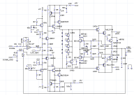
This is the high power blaster I've been working on designing. It's a relatively straightforward 3-tier class H, intended to deliver
something approaching 2kW/ch at 2 ohms. Why? Amps of this nature cost $1500 and up, and still don't really like 2 ohm loads so they're really more like 3 grand. It's intended to run on power supply components I got cheap in quantity - three 32.5-0-32.5 900VA trafos in series, with 68kuFx6 in reservoir capacitance. Top rail voltage is +/-138 similar to RMX4050, but with 2.5X the VA capacity in the supply it ought to do quite well. The circuit uses 9 pairs of MJL21193/4. Schematic shows one, but check the pcb layout. The topology is a triple darlington driven by a conventional Lin inside of an op-amp, with values I've tuned in over the years in several big class AB amps and recently verified with a smaller 2-tier version of this one. Rail switches are the same ones found in the QSCs and the clones, but with beefier commutation diodes and TO-247 packaged hexfets. Again, they use stuff I have on hand. Stability problems on the parent circuit have been identified and corrected - the circuit WILL NOT work with a quasi-complementary OPS, and fake MPSA56's should be
avoided 🙂.
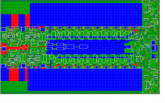
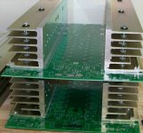
The problems I've been tackling recently on the design have been in manufacturability. Not that this is ever headed for an assembly line, but I have plans to build four this summer, and if I can get more trafos, up to four more. I managed to get it to fit in 14" so the pcb cost would be reasonable. I just got them in last week - about $27 each from Sunstone. The design had to use a heat sink arrangement that can be obtained surplus and machined on a table saw. And it all has to fit in 4U. It is intended to be used with a daughterboard front end which couples to both channels and does the housekeeping - filtering, clip limiting, bridging, and the balanced inputs. This board is not yet fabbed, but will be shared with some other designs I've been working on. Another board, to be designed, will handle all the protection with the exception of SOA limiting which is on the main board. Main signal and ground go through the center of the board, while the HS's at rail potential go down each side. The thermal compensation is the same as Leach used, with two diodes on one heat sink
and two on the other, so differences in temperature do not cause runaway. I have found this to be essential on previous designs. The two boards (one for each channel) will be stacked with insulators between them, and between them and the chassis. The chassis will use two fans - one to suck air down one side and the other to exhaust it out the opposite side with flow directors forcing the airflow along the heat sinks. I have used this arrangement before with good results.
Note: This project is under construction and subject to change if there are problems. It is not for first time builders as the results of mistakes can be hazardous to persons or property. When all is said and done, final schematics and gerbers will be made available. Bigger and badder things are in work, but this stepping stone will be crossed first.
something approaching 2kW/ch at 2 ohms. Why? Amps of this nature cost $1500 and up, and still don't really like 2 ohm loads so they're really more like 3 grand. It's intended to run on power supply components I got cheap in quantity - three 32.5-0-32.5 900VA trafos in series, with 68kuFx6 in reservoir capacitance. Top rail voltage is +/-138 similar to RMX4050, but with 2.5X the VA capacity in the supply it ought to do quite well. The circuit uses 9 pairs of MJL21193/4. Schematic shows one, but check the pcb layout. The topology is a triple darlington driven by a conventional Lin inside of an op-amp, with values I've tuned in over the years in several big class AB amps and recently verified with a smaller 2-tier version of this one. Rail switches are the same ones found in the QSCs and the clones, but with beefier commutation diodes and TO-247 packaged hexfets. Again, they use stuff I have on hand. Stability problems on the parent circuit have been identified and corrected - the circuit WILL NOT work with a quasi-complementary OPS, and fake MPSA56's should be
avoided 🙂.
The problems I've been tackling recently on the design have been in manufacturability. Not that this is ever headed for an assembly line, but I have plans to build four this summer, and if I can get more trafos, up to four more. I managed to get it to fit in 14" so the pcb cost would be reasonable. I just got them in last week - about $27 each from Sunstone. The design had to use a heat sink arrangement that can be obtained surplus and machined on a table saw. And it all has to fit in 4U. It is intended to be used with a daughterboard front end which couples to both channels and does the housekeeping - filtering, clip limiting, bridging, and the balanced inputs. This board is not yet fabbed, but will be shared with some other designs I've been working on. Another board, to be designed, will handle all the protection with the exception of SOA limiting which is on the main board. Main signal and ground go through the center of the board, while the HS's at rail potential go down each side. The thermal compensation is the same as Leach used, with two diodes on one heat sink
and two on the other, so differences in temperature do not cause runaway. I have found this to be essential on previous designs. The two boards (one for each channel) will be stacked with insulators between them, and between them and the chassis. The chassis will use two fans - one to suck air down one side and the other to exhaust it out the opposite side with flow directors forcing the airflow along the heat sinks. I have used this arrangement before with good results.
Note: This project is under construction and subject to change if there are problems. It is not for first time builders as the results of mistakes can be hazardous to persons or property. When all is said and done, final schematics and gerbers will be made available. Bigger and badder things are in work, but this stepping stone will be crossed first.
Attachments
Do you plan on listening inside a football stadium? 😉 You might as well look into a 3 phase feed...
Hi wg_ski,
this baby turns me on 😎
I'm also interested in building such a 'mean machine'.
A rail switcher was also what I admired, 'cause of the relatively low wast of power or, in other word, the efficiency.
And to "look into a 3 phase feed" (what astouffer mentioned) was anyhow my way of powering it, but still with the option to use 2 phase feeds. 😀
Well this would require three transformers (as you already mentioned), but hey, no work no fun.
And now arises a question:
When I take a glance at your main schematic, I see darlingtons made up of three transistors: 2SC4793 + MJL21194 + MJL21194 and 2SA1837 + MJL21193 + MJL21193, which give 6 BE-diodes in series. For the idle current stabilization circuit I see just 6 diodes in series which are in parallel to 4 BE-diodes of the 2SC4793s + 1k + 2k trimmer.
What worries me are the 6 diodes in series?!?
Considering a necessary voltage drop across the emitter resistors of the power MJLs, there will be no chance that an idle current will flow through them. Without those 6 diodes it would work - but right now I have my doubts. However it's still under construction, as you said yourself. 😉
Furthermore I'm going to dig in my QSC schematics and let's see what I can figure out myself. 😉
The six diodes (1N4148's) are the failsafe in case the vbe multiplier opens up. They are mounted to the PCB directly. It may take seven, to be determined by experiment. The idea is to have the the multiplier set the current and if something goes wrong the stack will clamp it. The ones in the collector circuit (diode connected transistors) of the vbe multiplier get mouted to the heatsinks - one at each end of each sink. Wires can get broken off, and if that happens the bias current should get railed short of two amps per transistor. A lot, but it can be shut down before anything really nasty happens.
You won't find this in the QSC circuits (but the rail switches are).
You won't find this in the QSC circuits (but the rail switches are).
Hi wg-ski,
You have been up to no good! More power than me...!😡
Neat. For power supply, I don't even know if this would work properly, but it something I've been thinking about: have you considered a full bridge doubler? A single, high VA 50-0-50 would give the same voltage as your 3, 32-0-32. Have to be 1.5-2kVA, no?
A thought. 🙂
@MJL21193:
Are you serious about considering a full bridge doubler?
At these high power reatings a 'doubler' isn't such a good idea. For auxiliary voltage supplies I wouldn't mind but not in a high current power path.
The use of 3 transformers is (in particular) a good idea when using 3 phase star connected feeds, with the star point connected to 'neutral'. This way you can switch between 2 phase and 3 phase feeds. For two phase feeds all three transformer are paralleled at the primary side.
@wg_ski:
Besides using heavy-duty toroidal transformers I'm considering to use (for simplicity reasons) a (no-feedback) SMPS with PFC. 😎
This way it might be possible to keep the whole amp below a weight of 30 pounds. And more interesting, for global use the input voltage would be of no interest (wide range input, i.e. from 90...240VAC). I've a particular design in mind and if you (and other too of course) are interested I'm going to share my thoughts and we can discuss the (final) design based on wishes, ease of design, reliability, and so on.
Just curious: What will be the use of the amp? 2000 W in the living room or as PA? If in the living room, how high audio level do you want to achieve? 
In my case it would be PA use only, (loud  ) garden partys, other 'smaller' PA events and also for rent (therefore not only for my own pleasure).
For my living room I've already a good amp (of course DIY) and my own reference speakers (also DIY of course). 🙂
Loudspeakers I build my own, preferably horns for the bass. I like it really 'rumbling' (if you know what I mean). 😀 😀 😀
) garden partys, other 'smaller' PA events and also for rent (therefore not only for my own pleasure).For my living room I've already a good amp (of course DIY) and my own reference speakers (also DIY of course). 🙂
Loudspeakers I build my own, preferably horns for the bass. I like it really 'rumbling' (if you know what I mean). 😀 😀 😀
Corax said:@MJL21193:
Are you serious about considering a full bridge doubler?
At these high power reatings a 'doubler' isn't such a good idea. For auxiliary voltage supplies I wouldn't mind but not in a high current power path.
The use of 3 transformers is (in particular) a good idea
Hi Corax,
Yes, I am serious. A doubler would double the voltage and half the current, right? So you start with more current. Seems simple to me, but maybe I'm not seeing it correctly. Can you explain why it would not be a good idea?
Without a doubt, the best option would be a single, massive transformer, rather than three separate units. One bigger is always more efficient than three smaller. These are costly though.
Corax said:@MJL21193:
Besides using heavy-duty toroidal transformers I'm considering to use (for simplicity reasons) a (no-feedback) SMPS with PFC. 😎
This way it might be possible to keep the whole amp below a weight of 30 pounds. And more interesting, for global use the input voltage would be of no interest (wide range input, i.e. from 90...240VAC). I've a particular design in mind and if you (and other too of course) are interested I'm going to share my thoughts and we can discuss the (final) design based on wishes, ease of design, reliability, and so on.
Thought about SMPSs, but I'm just not as qualified as Eva is to build them. Especially not at this power level - 60 Hz units are foolproof and I already have them. Most of the "design" consists of taking known working sub-circuits putting them together around what I can buy surplus. I found the trafos, did some quick cals that said they will do a "super heavy duty RMX4050-like amp", and bought them all. They've been sitting while I figured out how to fit everything together. In the meantime, I built a smaller amp (4x750) using similar circuits with only a single rail switch to make sure everything will work together before doing board layout. I have enough extra pcbs to build a few more of this same amp if I can come up with a good SMPS.
peranders said:Just curious: What will be the use of the amp? 2000 W in the living room or as PA? If in the living room, how high audio level do you want to achieve?
Of course it'f for PA, silly. I have eight sub boxes, eight midbass boxes, and six mid/hi cabs driven with three S-Leach type 1.2kW/ch units, two PLX3102s, two XS1200's and a CE4000. It's not enough power to do it right, and I keep having to rob amps from this system to rent out my smaller one (which is a lot more often). A couple of RMX2450's and USA1310's have been relegated to monitor duty.
MJL21193 said:
Yes, I am serious. A doubler would double the voltage and half the current, right? So you start with more current. Seems simple to me, but maybe I'm not seeing it correctly. Can you explain why it would not be a good idea?
Without a doubt, the best option would be a single, massive transformer, rather than three separate units. One bigger is always more efficient than three smaller. These are costly though.
Voltage doubler? No way. The peak currents will be ridiculous, and the filtering requirements for 60 Hz ripple will be out of this world. The voltage will drop like a stone under load and I'll be lucky to get 1kw/ch at 2 ohms out of the same volatges with the same AC power draw. A single massive trafo would be the best possible way to go, but I obtained the 32-0-32's for $30 apiece. Try to get a 2.5kVA six-secondary custom would toriod and see what it costs ya. Enough to make you just drop the whole idea and drop three grand for a *pair* of RMX4050's. You'll still be ahead buying three 800-900VA standard units.
some progress
It took a while to figure out how to build this in a manner that's repeatable, using stuff that I can get and tools I have. Next up, start stuffing the first board, and cutting holes in the chassis.
The first one should be up by June or July.
It took a while to figure out how to build this in a manner that's repeatable, using stuff that I can get and tools I have. Next up, start stuffing the first board, and cutting holes in the chassis.
The first one should be up by June or July.
Attachments
Hi
Look at rockford fosgate, biggest amp, but still in class AB, but I would go for D, but it is not easy to make it stable
Look at rockford fosgate, biggest amp, but still in class AB, but I would go for D, but it is not easy to make it stable
Re: some progress
Isn't it better to have a couple smaller amps? It must be easier to find semiconductors.
Have you seen the nice and small amps from Labgruppen
13000 watts!
More class D
Nice amps
2 kW/channel => 1.5 kW heat. That's a lot! Your cooling scheme seems not to be sufficient for the task.wg_ski said:It took a while to figure out how to build this in a manner that's repeatable, using stuff that I can get and tools I have. Next up, start stuffing the first board, and cutting holes in the chassis.
The first one should be up by June or July.
Isn't it better to have a couple smaller amps? It must be easier to find semiconductors.
Have you seen the nice and small amps from Labgruppen
13000 watts!
More class D
Nice amps
Re: Re: some progress
Actually, about 900 watts heat. 3-tier class H. And this has more heatsink than comparably rated commercial offerings (which is why they can't put out over 1/8 power).
A couple of smaller amps? I'm planning a rack full of these as it is.
Which is why I'm taking the time to make it easily manufacturable.
I'd love to have a half dozen Lab Gruppens. But I decided to pay off my house instead of spending that kind of money on amps.
peranders said:
2 kW/channel => 1.5 kW heat. That's a lot! Your cooling scheme seems not to be sufficient for the task.
Isn't it better to have a couple smaller amps? It must be easier to find semiconductors.
Actually, about 900 watts heat. 3-tier class H. And this has more heatsink than comparably rated commercial offerings (which is why they can't put out over 1/8 power).
A couple of smaller amps? I'm planning a rack full of these as it is.
Which is why I'm taking the time to make it easily manufacturable.
I'd love to have a half dozen Lab Gruppens. But I decided to pay off my house instead of spending that kind of money on amps.
goon mate
who cares if i would be listening to a million watt amp rumbling in my bed room
and heat is just very easy to overcome........well provided that there are no oscillations or the amp is stable..........
and pls....frankly who wants to have a cup of cold coffee.......
as class D is........
served cold ? naaahhh......
can't wait for the results!
- Status
- Not open for further replies.
- Home
- Amplifiers
- Solid State
- Multi-kilowatt blaster in development