Width of the slot. You will end up with a bunch of square cavities. Imagine 4 dual woofer baffles stacked on top of each other. You couldeven buildit that way.
dave
Thanks, so brace between slots to close the slots and make 4 rectangles basically? I can do that if it's superior. A single slot would be easier of course, but a few braces isn't that much extra work to cut and place at least for testing.
Very best,

quarter wavelength of 150Hz is 23 inches so that is the upper frequency limit. If your cavity is 24" or so deep with 2 12" woofers, the limit is less than 150Hz.
Thanks, so that's good and within goal range then.
Very best,
Hi all,
I was able to build a physical model of just two drivers (this will scale to 8 total eventually) and do some tests on cavity width and all that. Crudely.
Baffle dimensions, W-frame with a slot:
Effective baffle width: 12" + 9" + 12" + slot width + 12" + 9" + 12" = 68.5" width for the 2.5 inch slot, and 72" width for the 6 inch slot.
Front baffle total width is only 9" + slot width + 9". So 21" to 24" actual width.
Height is 12" plus material thickness. But will scale to 8, so it will be closer to 55~60 inches total height.
Depth is 12.5" roughly, but will have a lip around the base.
Approximately 3 inch width on the slot here:


Approximately 6 inches slot width here:


Here's the ~ 3 inch slot width results at different SPL levels to examine things, near field, 10hz to 400hz.

Here's the 6 inch wide slot results at different SPL levels, near field, 10hz to 400hz, with a wider effective baffle.

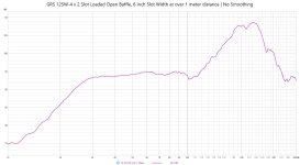
Here's the 6 inch slot width, but with a > 1 meter measurement distance to just to see if any boundaries were influencing things differently compared to the near field at the slot. No smoothing. Noted that the cavity resonance SPL is higher as the overall SPL of course drops, but it stays pretty flat to 29~30hz range here so that's a good sign I think. No DSP.

Cavity resonance spikes. The ~2.5~3 inch slot width gave me a peak near 235hz. The 6" slot had an artifact from my crude assembly, but if we extrapolate from the curves, it's peak is lower in frequency as expected from the larger width.

I aligned them at 31hz here, ignore the SPL, I didn't scale it correctly there. I just wanted the curves to line up around 30~31hz and see the differences from there. The 6 inch cavity resonance will peak earlier, but still well above 100hz. 3 inch cavity resonance peaks above 200hz, even better. The smaller slot shows a better F3 and a bit more extension under 30hz. If we're at 31hz as a peak before it rolls off, somewhere around 22~23hz is only -3db below that. This is pretty interesting.

I will build a full size prototype next and get better measurements.
Very best,
I was able to build a physical model of just two drivers (this will scale to 8 total eventually) and do some tests on cavity width and all that. Crudely.
Baffle dimensions, W-frame with a slot:
Effective baffle width: 12" + 9" + 12" + slot width + 12" + 9" + 12" = 68.5" width for the 2.5 inch slot, and 72" width for the 6 inch slot.
Front baffle total width is only 9" + slot width + 9". So 21" to 24" actual width.
Height is 12" plus material thickness. But will scale to 8, so it will be closer to 55~60 inches total height.
Depth is 12.5" roughly, but will have a lip around the base.
Approximately 3 inch width on the slot here:
Approximately 6 inches slot width here:
Here's the ~ 3 inch slot width results at different SPL levels to examine things, near field, 10hz to 400hz.
Here's the 6 inch wide slot results at different SPL levels, near field, 10hz to 400hz, with a wider effective baffle.
Here's the 6 inch slot width, but with a > 1 meter measurement distance to just to see if any boundaries were influencing things differently compared to the near field at the slot. No smoothing. Noted that the cavity resonance SPL is higher as the overall SPL of course drops, but it stays pretty flat to 29~30hz range here so that's a good sign I think. No DSP.
Cavity resonance spikes. The ~2.5~3 inch slot width gave me a peak near 235hz. The 6" slot had an artifact from my crude assembly, but if we extrapolate from the curves, it's peak is lower in frequency as expected from the larger width.
I aligned them at 31hz here, ignore the SPL, I didn't scale it correctly there. I just wanted the curves to line up around 30~31hz and see the differences from there. The 6 inch cavity resonance will peak earlier, but still well above 100hz. 3 inch cavity resonance peaks above 200hz, even better. The smaller slot shows a better F3 and a bit more extension under 30hz. If we're at 31hz as a peak before it rolls off, somewhere around 22~23hz is only -3db below that. This is pretty interesting.
I will build a full size prototype next and get better measurements.
Very best,
Attachments
I'm trying to understand why the phase measurements show this?

Vs a sealed arrangement:

Very best,
Vs a sealed arrangement:
Very best,
Go to control, right up, and unwrap the phase...
Thanks, phew, that was driving me nuts.

I liked the 3" slot width results here, so I'm started gluing the physical model together permanently so I can more rigorously measure it and do some ground plane measurements and I have a jig to measure excursion and will take the system to its excursion limits and see how all that looks and sounds.
Very best,
Looks like you are getting a bandpass response with both the 2.5in and 6in slots.
Did you try inverting 1 driver for lower distortion in the 6in slot?
I didn't invert a driver, I prefer both cones facing each other. The aesthetic as this is going to be a large sub and not tucked away and I don't want to see the little magnets and stuff. Plus all the wires that then have to go into the slots. I just don't' like that look.
When you describe it as bandpass looking, do you meant the resonance or the roll off under 27~28hz here? Are you suggesting it's possible to get a slower roll off? I wouldn't think that's possible on an open baffle due to the nature of it all.
So far, I like this response, it looks better than a typical sealed with a much higher F3. The slight rise towards 30hz is nice, a gentle natural house curve. This will end up DSP'd to a house curve 99% of the time in use for music anyways. But still, nice to already have it there. The resonance spike will be completely cut out with an aggressive low pass filter as the intended range is 10hz to 100hz, but will mostly focus on 27hz to 100hz as its primary bandpass.
Very best,
Update, new prototype finished. Measured.
21" wide, 13.5" tall, 13.5" deep. Internally about 1.6 ft^3 displaced. W-frame slot loaded open baffle
GRS12SW-4 x 2 ($31 each) wired in series (7.7 ohm)
DATS to see Fb and baffle resonance, noted the 225~240hz spike expected from the slot cavity resonance.

The crude form:


Measurements:
Ground plane 1 meter
First, I took my jig out and took them to peak to peak xmax over 16mm, and they were still going. Not clanking. So while I could keep pushing, I stopped, because while I could push past xmax without hitting xmech, it doesn't matter if it's not actually increasing SPL so I needed to see compression first and then see what power got me to that point.
First up, front wave facing the slot.

With the XLS 1002 I started at -28dbFS and went in 3db steps until I saw compression and then backed off until I saw 1db changes and measured at that point. Here you can see compression starting from 25.3hz and below, I didn't get the +3db gain, so I backed off. This happened at -16dbFS (first sign of compression).

I backed off to -17dbFS and re-ran it, got +1db without compression that I could see. So this was my "max ideal" basically. I then measured at -16dbFS again to see compression and one more at -15dbFS to see max compression and noted no more increase at all under 25hz, so this was my effective maximum excursion. If I killed off everything below 30hz, I could still push this thing for more output as you can see. But probably not much more.
So at -17dbFS I'm at my ideal output before compression kicks in hard. This is what I measured voltage at.
100.5db at 30hz at 1 meter
92.5db at 20hz at 1 meter
80.5db at 10hz at 1 meter
10hz to 20hz was a 12db change per octave (like sealed, not like open baffle!)
20hz to 40hz was a 9db change per octave (better than sealed and open baffle!)
30hz to 60hz was 3db change per octave (getting flat!)
Good to 27hz as wanted (lowest key on piano)

I kept my -17dbFS settings and output a 10hz sine wave constant. I hooked in with the mulit-meter to measure voltage. It was fluctuating between 15.5v and 16.4v back and forth. So I just called it 16v for approximation at this point. This is asking more from the amp than any frequency above it, so I figured this value is good for compression and effectively the highest the two drivers will take in this configuration before compression starts taking away output for the signal increase. 16v at 7.7ohm from the Crown XLS1002 with my input signal (low) from a USB DAC I was using. So while this wont' scale to other things, it just gave me a value to start considering for later tests.

Behind, the back wave.
The back wave however, isn't going to be equal (this is a goal) because it doesn't have the slot cavity, so it's not squeezing pressure out, it's loafing along out of those wide 9 inch open chambers and the slot depth is gone so its effective baffle width is lower, significantly (over 24" reduced just from this). So in theory, the back wave should have less energy because its asymmetrical and doesn't have the slot so lower energy. This is important, and this is why the slot cavity is essential: this effects how much energy from the backwave will come around and meet the front wave and start to cancel each other. The stronger wave will not be degraded as rapidly as normal and so roll off is reduced. Unlike a normal open baffle and unlike sealed.


The backwave at the same input signal and 1 meter distance is approximately 2db lower. This is why there's less cancellation to the front wave and the response is what it is instead of the nasty -18db/oct roll off open baffle normally would have. This is due to the slot energy and extra baffle width.
Off axis, 90 degrees, where cancellation is high. Measured from the acoustic center of the slot.

Here is the front wave, backwave and the off axis waves at all the same signal level. This confirms I still have a dipole. Off axis is heavily canceling and only the slot itself and its resonant peak maintains energy. Around a good 20~25db drop in SPL when off axis. But I could hear the slot resonance easily, like a siren belting at 115~123db at 225~240hz, loud. I will cut that with low pass filter of course. But this was to confirm dipole behavior and it is maintained.

Lastly a look at phase to ensure I didn't make a bandpass by accident.

Finally decay, at max signal from before (before compression) to look for any structural problems and driver behavior problems like resonance and ringing. Noise floor was 52db outside today with a gentle breeze. But some hedge, trees, etc, a few feet away that don't effect infrasonic and subbass, but obviously effect upper frequencies, so I could see that here at 70hz and up.

And here, to see the ringing from the slot cavity's resonance, it's clearly ringing and not decaying at 300ms time in that 225~240hz range where the slot's output peaks. But above that it starts to drop off again. Just confirms behavior of the slot and resonance.

Now I will listen (low pass at 100hz aggressively) for a while and contemplate what will change in prototype 2 before I scale it to 8 drivers total.
Very best,
21" wide, 13.5" tall, 13.5" deep. Internally about 1.6 ft^3 displaced. W-frame slot loaded open baffle
GRS12SW-4 x 2 ($31 each) wired in series (7.7 ohm)
DATS to see Fb and baffle resonance, noted the 225~240hz spike expected from the slot cavity resonance.
The crude form:
Measurements:
Ground plane 1 meter
First, I took my jig out and took them to peak to peak xmax over 16mm, and they were still going. Not clanking. So while I could keep pushing, I stopped, because while I could push past xmax without hitting xmech, it doesn't matter if it's not actually increasing SPL so I needed to see compression first and then see what power got me to that point.
First up, front wave facing the slot.
With the XLS 1002 I started at -28dbFS and went in 3db steps until I saw compression and then backed off until I saw 1db changes and measured at that point. Here you can see compression starting from 25.3hz and below, I didn't get the +3db gain, so I backed off. This happened at -16dbFS (first sign of compression).
I backed off to -17dbFS and re-ran it, got +1db without compression that I could see. So this was my "max ideal" basically. I then measured at -16dbFS again to see compression and one more at -15dbFS to see max compression and noted no more increase at all under 25hz, so this was my effective maximum excursion. If I killed off everything below 30hz, I could still push this thing for more output as you can see. But probably not much more.
So at -17dbFS I'm at my ideal output before compression kicks in hard. This is what I measured voltage at.
100.5db at 30hz at 1 meter
92.5db at 20hz at 1 meter
80.5db at 10hz at 1 meter
10hz to 20hz was a 12db change per octave (like sealed, not like open baffle!)
20hz to 40hz was a 9db change per octave (better than sealed and open baffle!)
30hz to 60hz was 3db change per octave (getting flat!)
Good to 27hz as wanted (lowest key on piano)
I kept my -17dbFS settings and output a 10hz sine wave constant. I hooked in with the mulit-meter to measure voltage. It was fluctuating between 15.5v and 16.4v back and forth. So I just called it 16v for approximation at this point. This is asking more from the amp than any frequency above it, so I figured this value is good for compression and effectively the highest the two drivers will take in this configuration before compression starts taking away output for the signal increase. 16v at 7.7ohm from the Crown XLS1002 with my input signal (low) from a USB DAC I was using. So while this wont' scale to other things, it just gave me a value to start considering for later tests.
Behind, the back wave.
The back wave however, isn't going to be equal (this is a goal) because it doesn't have the slot cavity, so it's not squeezing pressure out, it's loafing along out of those wide 9 inch open chambers and the slot depth is gone so its effective baffle width is lower, significantly (over 24" reduced just from this). So in theory, the back wave should have less energy because its asymmetrical and doesn't have the slot so lower energy. This is important, and this is why the slot cavity is essential: this effects how much energy from the backwave will come around and meet the front wave and start to cancel each other. The stronger wave will not be degraded as rapidly as normal and so roll off is reduced. Unlike a normal open baffle and unlike sealed.
The backwave at the same input signal and 1 meter distance is approximately 2db lower. This is why there's less cancellation to the front wave and the response is what it is instead of the nasty -18db/oct roll off open baffle normally would have. This is due to the slot energy and extra baffle width.
Off axis, 90 degrees, where cancellation is high. Measured from the acoustic center of the slot.
Here is the front wave, backwave and the off axis waves at all the same signal level. This confirms I still have a dipole. Off axis is heavily canceling and only the slot itself and its resonant peak maintains energy. Around a good 20~25db drop in SPL when off axis. But I could hear the slot resonance easily, like a siren belting at 115~123db at 225~240hz, loud. I will cut that with low pass filter of course. But this was to confirm dipole behavior and it is maintained.
Lastly a look at phase to ensure I didn't make a bandpass by accident.
Finally decay, at max signal from before (before compression) to look for any structural problems and driver behavior problems like resonance and ringing. Noise floor was 52db outside today with a gentle breeze. But some hedge, trees, etc, a few feet away that don't effect infrasonic and subbass, but obviously effect upper frequencies, so I could see that here at 70hz and up.
And here, to see the ringing from the slot cavity's resonance, it's clearly ringing and not decaying at 300ms time in that 225~240hz range where the slot's output peaks. But above that it starts to drop off again. Just confirms behavior of the slot and resonance.
Now I will listen (low pass at 100hz aggressively) for a while and contemplate what will change in prototype 2 before I scale it to 8 drivers total.
Very best,
This is my EQ/DSP response. I killed the cavity resonance with a low pass filter at 120hz 24db/oct. I also set a fairly heavy -PEQ on about 235hz by -6db or so. You can still see the spike at 240hz range in the measurement, but it's greatly reduced. I'll get it perfect in a few more setting tweaks and have it fully gone. I don't hear it as it is though. I raised the low end at 20hz to get a good heavy house curve. Left everything under 10hz alone. Overall, it sounds great, music is just thumping along, it's not lacking in SPL, it's quite loud, and the slot has great energy coming from it, high air velocity, lots of acceleration going on between the drivers and the slot air velocity, it really "slams" and moves my shorts. Fun! So with this, I will start designing the next iteration with 8 drivers total in a tower. Basically 4 of these stacked, but one structure.
Very best,
Hello. Especially interesting to follow your thread. I plan to make a slob solution with 2 x 12" myself.
A bit critical of the volume at the rear of your drivers. Such solutions should preferably be somewhat in relation to each other.
Please take a look at this one; https://jazzman-esl-page.blogspot.c...8qfucwhb8g9x7CLdkg_aem_inciIZJHOqW44vwIfKIPLg
A bit critical of the volume at the rear of your drivers. Such solutions should preferably be somewhat in relation to each other.
Please take a look at this one; https://jazzman-esl-page.blogspot.c...8qfucwhb8g9x7CLdkg_aem_inciIZJHOqW44vwIfKIPLg
Hello. Especially interesting to follow your thread. I plan to make a slob solution with 2 x 12" myself.
A bit critical of the volume at the rear of your drivers. Such solutions should preferably be somewhat in relation to each other.
Please take a look at this one; https://jazzman-esl-page.blogspot.c...8qfucwhb8g9x7CLdkg_aem_inciIZJHOqW44vwIfKIPLg
This is just my proof of concept prototype, to learn from. This will scale to 8 drivers. The volume behind the drivers is to make room for the material I plan to put inside the wings on a much taller, 55 inch version of this, with 4 drivers per side of the slot cavity. The slots will be individual per driver pair. 4 total pairs. It will be about 21" wide, 55" tall, 14" deep. And I plan a footer. Slots will be 3" x 10~11" roughly each, and 12" deep. I may add material into the slots to fill their volume more.
Ideally I would like to see even less energy from the backwave of the design. I'm not sure how to do that other than further increasing energy on the front wave. So I will make a new prototype with 4 slots and 8 drivers and see if the front wave scales higher and the if the back waves are still 2db less or different.
If you have suggestions, I'm happy to hear them. Or ideas and theory. This is new to me in general and I cannot simulate these properly so I have to just build models and measure them and listen to them to see what happens.
Very best,
Hi,
maybe I missed something crossreading this thread, but I can't seem to see Ridthaler (Ripole) and Borbely cited.
Over the years their folded w-dipoles have been talked, simmed, built and tested ... so rather nothing new to be found.
This design here looks suboptimal to me.
The large back chamber appears more like a Borbely design, but the small front chamber is more of an Ripole.
Still though the front chamber looks probabely just too small, resulting in an unwanted efficiency loss.
The back and front chamber relation seems a bit disproportioned, not optimally capitalizing on the Fs- sinking property of a (smaller) Ripole, and reducing efficiency of a (larger) Borbely.
jauu
Calvin
Hi,
maybe I missed something crossreading this thread, but I can't seem to see Ridthaler (Ripole) and Borbely cited.
Over the years their folded w-dipoles have been talked, simmed, built and tested ... so rather nothing new to be found.
This design here looks suboptimal to me.
The large back chamber appears more like a Borbely design, but the small front chamber is more of an Ripole.
Still though the front chamber looks probabely just too small, resulting in an unwanted efficiency loss.
The back and front chamber relation seems a bit disproportioned, not optimally capitalizing on the Fs- sinking property of a (smaller) Ripole, and reducing efficiency of a (larger) Borbely.
jauu
Calvin
Hi,
Nothing cited, I had some help trying to figure out some modeling in the Horn Resp thread, but then figured I needed to try some physical models and measure them. I'm not breaking new ground, just standing on the shoulders of giants. I am just trying to have fun and try something new. I like to learn something along the way. So any info you can share is greatly appreciated.
I tried the larger cavity chamber, 6 inches, and you can see my measurements there vs the smaller cavity chamber at 2.5~3.0 inches. I didn't see a compelling difference to use the larger cavity, but maybe that was because of other parts of the design in general. So I'm curious how the larger cavity would reslut in more efficiency if you can share something on that, it would be helpful.
I went smaller on the front chamber because of the large depth of the cavity and overall large volume in the cavity using 12" drivers. Looking at other people's slot loaded opposed drivers like this, none of them have huge 6+ inch wide slot cavity widths, so the 33% rule of thumb from Pass's documentation as a rule of thumb didn't seem like it was going to be used here with larger drivers and was mostly shown only with small drivers. So I had to experiment. That's why I did a 6 inch vs 3 inch slot and measured them both. I didn't see a difference that was significant in the measurements, so I opted to keep it smaller to reduce the overall size of the future tower width.
If you can help with appropriate chamber sizes to lower Fs, I'm happy to learn more about it. I'd love to measure Fs lowering but I can't seem to do that and rather need to just see it in measurements of the response at higher SPL to see it in action which seemed to show up in some measurements as the roll off descended farther down, and was getting good response to 27hz.
Any help appreciated and I can try to make a physical model and test it.
Very best,
When you describe it as bandpass looking, do you meant the resonance or the roll off under 27~28hz here? Are you suggesting it's possible to get a slower roll off? I wouldn't think that's possible on an open baffle due to the nature of it all.
So far, I like this response, it looks better than a typical sealed with a much higher F3. The slight rise towards 30hz is nice, a gentle natural house curve. This will end up DSP'd to a house curve 99% of the time in use for music anyways. But still, nice to already have it there. The resonance spike will be completely cut out with an aggressive low pass filter as the intended range is 10hz to 100hz, but will mostly focus on 27hz to 100hz as its primary bandpass.
Very best,
The whole curve... 27hz & 250hz roll offs.
Bandpass rules!
The whole curve... 27hz & 250hz roll offs.
Bandpass rules!
It does sort of look like a 4th order with a large front chamber that is too efficient actually!
Very best,
The way you have made the prototype, this is a SLOB design and it has been well tried. But you have to stick to certain factors. The back chamber port must be a area between 1/2 to 1 of both pistion driver area. Front gap 1/3 area of both pistion driver area when X max greater than 10 and 1/4 when X max less than 10.
Stick to these well-tried factors and this will work, even with several built in height.
Stick to these well-tried factors and this will work, even with several built in height.
The way you have made the prototype, this is a SLOB design and it has been well tried. But you have to stick to certain factors. The back chamber port must be a area between 1/2 to 1 of both pistion driver area. Front gap 1/3 area of both pistion driver area when X max greater than 10 and 1/4 when X max less than 10.
Stick to these well-tried factors and this will work, even with several built in height.
Interseting thanks!
So, with these 12" drivers, xmax rated at 8mm (it goes farther though, but lets just stay at 8mm), Two of them have a combined area of 226 square inches, so 25% of that area would be 56.5 square inches. The slot will be assumed 12" high, so that leaves a slot width of 4.7 inches. At 33% it would be 6.25 inches. This is why I did the 6 inch prototype and measured it. I didn't see a compelling reason to stay 6 inch. Maybe something else was keeping my measurements too similar?
So the back chamber, at 0.5 to 1.0 area of both drivers would be 57 square inches to 113 square inches, which with a 12" height and 12" depth (for the driver) leaves me with a 9 inch chamber width. That's what width each chamber is here. So you're saying this is too small? Or did I calculate this incorrectly?
Very best,
- Home
- Loudspeakers
- Subwoofers
- Multi-Driver-Opposed Open Baffle Subwoofer Questions