Just finished it! I haven't had time to until now. Wow, this things are even more complicated than imagined, Oh well.
Eli, I also see mention of the 12B4. That is interesting as I have several sleeves in wait for a preamp. I even have some OD3's to feed them. That would make a very pretty Monoblock!
Eli, I also see mention of the 12B4. That is interesting as I have several sleeves in wait for a preamp. I even have some OD3's to feed them. That would make a very pretty Monoblock!
Now you are talking some serious current as you want to pass almost as much current through the OD3 as the device to get decent regulation.
12b4 has its issue too with its high current. But I am game to make it work.
Its not really complicated but a GREAT learning excersize.
I just posted on that thread my first attempt at calculating a feedback resistor. I am curios to see how wrong I am. ;-) Ignore the complexity of the schema it is mainly an exploration.
I looking at the 12bh7 now.
Lets see what Johan's data shows on the ef86.
Last edited:
Just finished it! I haven't had time to until now. Wow, this things are even more complicated than imagined, Oh well.
Eli, I also see mention of the 12B4. That is interesting as I have several sleeves in wait for a preamp. I even have some OD3's to feed them. That would make a very pretty Monoblock!
The 12B4 is a great tube, BUT it's out of production. Also, 12B4 current demands on the PSU are quite substantial.
FWIW, I'd save the 12B4 specimens for line stage service and use the current production EH 12BH7, as the voltage amplifier. Maybe you could arrange a NOS swap.
The 12B4 is a great tube, BUT it's out of production. Also, 12B4 current demands on the PSU are quite substantial.
FWIW, I'd save the 12B4 specimens for line stage service and use the current production EH 12BH7, as the voltage amplifier. Maybe you could arrange a NOS swap.
Yes, it would be a shame to have another popular build eat more of the 12B4 supply, driving of costs.
Last edited:
As members may recall, this was an exercise to determine best working point and distortion for several twin triodes for use as LTP phase inverters in the design under discussion. Since I did not have all the tubes to practically test, the arithmetric method outlined in the Steve Bench site mentioned before was used. (http://greygum.net/sbench/sbench102/pc-dis.html ).
Fairly early in the excercise it was realised that this method is not very accurate, as it uses the small difference between large figures read off the tube graphs. I searched for clear Ia-Va graphs and enlarged the relevant portions (but then the lines also become thicker!). Because of this it was also necessary to obtain the five points needed directly off a [-Vg1] curve; interpolating would make the readings even less accurate. For this reason I could not include certain tubes (e.g. 6H6/6N6), where enough Vg1 curves were not given. I obtained the following values:
TUBE......Va(V)..Ia(mA)....A.....%D2.....%D3.....%D4....f(-3dB)
ECC99.....235.....3,2.......9........4.........7,9......0.........35kHz
5687.......215.....4.........7,5......6.........0........0,7.......53kHz
6GK5.......233.....5,4......22......6,9.......1,5......0,8.....100kHz
12AT7.....276.....3,4......14......9,8.......6,5......4,5.......78kHz
ECC88.....235.....3,6......13......1,7.......4,5......4.........78kHz
E182CC...237.....3,75.....10......2,5.......0........1,6.......29kHz
Explanation:
100V was taken as departure for the LTP cathodes voltage (fed from the preceeding EF86). Thus the Va values shown are actually 100V higher than the nett voltage between anode and cathode. Amplification factor A is as in the LTP, i.e. half of the gain of one tube. 2nd, 3rd and 4th harmonics are given, after fitting the 100Vpp signal required for the KT88s in the best position on the load line. (The description of what a load line is is given in the Bench article above. Some further elucidation in a later post.) The frequencies given are where the -3dB h.f. cut points will be. These results mainly from the LTP Miller effect onto an equivalent EF86 feeding impedance of some 88K. The capacitive loading of the KT88 inputs was not taken into account.
Discussion:
Visually the ECC99 stands out as quite linear; the %3rd harmonic is a surprise. (I will discuss the linearity by visual impression later; I have a feeling from some past posts that there is some misunderstanding there.) The lowest is expectedly the E182CC, because it has the largest anode swing. (The lowest Va-c is a surprising 10V only, at 2mA anode current!). It thus uses a smaller % of available anode swing than other triodes. But the high Miller capacitance! That is a secondary deterrent, depending on the rest of the circuit and the designer's proficiency at making NFB stable.
In contrast the 6GK5 exhibits a very low Miller capacitance because of the fine wire used in the frame grid construction of G1. That gives a high h.f. turn-down point, easing life from gNFB point. It also makes it a good input triode (in place of EF86), placing the usual doubts about the input tube Miller effect on unknown input feeding impedances very low on the list of worries. Distortion at input signal level should be quite low.
The 12AT7 unfortunately suffers from the needed output signal amplitude taking up most of its available 'headroom'. It also ties in with a strange non-linearity at bias 0 - 1,5V, clearly visible on the Ia-Va vs [-Vg1] graph family.
Eli's preference for this tube has been noticed; one can have more accurate readings if one is fortunate to have a good spectrum analiser (still on my wish-list!). It is also my general preference for lower grid drive p.p. stages. I did point out some posts ago that it suffers to supply the 100Vpp required signal. I also then said that the EF86 can be operated at lower Va to give the 12AT7 more headroom. (As low as Va=50V is feasible.)
For now, the choice is a judgement call between opposing factors (surprised?) For myself, I reckon ECC88 is a fair choice, but if an input triode is preferred (lower feeding impedance to the LTP), the E182CC might be the choice. 6GK5 steps up, but that would mean two tubes for the LTP.
I would like to discuss a few further factors that play a role, for particular elucidation for those not too conversant with tube design. That in a further post - this is becoming long.
Johan,
Nice table, thank you.
6GK5 is indeed a good tube, but it's overload capacity is very poor since there is less than a volt grid bias at the operating point. Use with care.
Hugh
Nice table, thank you.
6GK5 is indeed a good tube, but it's overload capacity is very poor since there is less than a volt grid bias at the operating point. Use with care.
Hugh
OOPS!
I see that my reference for the Steve Bench site was wrong. (See post#378 by Boywonder.) It should be:
Of Loadlines, Power Output and Distortion.
I see that my reference for the Steve Bench site was wrong. (See post#378 by Boywonder.) It should be:
Of Loadlines, Power Output and Distortion.
Hugh,
Good point. But I hope this is not a "Here we go again" matter - as in different graphs/specs by different manufacturers! I found and mentioned that earlier.
The 6GK5 graphs I used were from GE. Their spec. sheet reference is 'ET-T3052' and on the Ia/Va family given on their page 3 (top), I find that my chosen operating point of Va = 133V at Ia = 5,4mA, falls exactly on the Vg = -1,5V curve. It could possibly go to a little higher [-Vg], but at Vg = -2V (Va = 168V and Ia = 3,6mA), the anode high swing runs into a high 2nd harmonic zone on the ac load line (somewhat difficult to read off on a crowded graph sheet). It would appear that the KT88s would run out of working range before a 6GK5 LTP might - but in an overload situation I find it difficult to estimate what really would amount to what. That is where practical tests with a spectrum analyser will be the only indication - apart from hearing!
But your point is taken. (That is why I dislike using a 12AX7 for this sort of function. Its working bias IS really very limited in some designs.)
While I am typing, I should have mentioned that the Ia given in that table, is for a single triode. For the LTP tail current setting therefore, double that value must be set for.
Lets see what Johan's data shows on the ef86.
Sorry SGregory, my 'investigation' (outlined in a post above) did not include the EF86. That is a whole different ball-game. I can now only say that I have used the EF86 before with as low a Va = 55V and Vg2 = 45V, with a 10megohm self-bias G1 resistor, in low amplitude situations (pre-amps). In the present situation the signal it must deliver is some 10Vpp max. - perhaps on the fringe of what can still be called low amplitude. (Using sharp cut-off pentodes in the grid-leak (G1) mode gives lowest distortion at low to moderate output amplitudes. Also to repeat: At low signal levels proper pentode operation can be up to four times more linear than triodes, when fed from low input sources. But distortion in those stages are much lower than the output distortion anyway, thus not too important in the total picture.)
I think 'bed' here now. (The post time is also our time.)
Good point. But I hope this is not a "Here we go again" matter - as in different graphs/specs by different manufacturers! I found and mentioned that earlier.
The 6GK5 graphs I used were from GE.
No Kidding.. In my incredibly limited experience with load lines I recently noticed that the 6GK5 GE data is quite a bit different from the RCA data. Based on Poindexter's implementation in his music machine, I also came to the conclusion that the GE data made more sense.
Johan: Thank you for taking the time to do the above analysis. Please continue to walk us newbies through the choices and trade-offs for the first stage and LTP.
Johan,
1.5V Vgk is not too bad, I agree. Normally I find this will overload around 1.5 times Vgk, that is, 2.25Vp. This is, of course, a substantial signal.
You use a very low current. I'd found in a hybrid amp some years back that it seemed to deliver best sound around 9mA. Have you found this? Of course, 'best sound' is subjective, may not directly relate to H2/H3, so is a moot point..... The tube has marvellous gain.
Hugh
I don't mind FETs in the design. But it does complicate the construction as a DIY project. Not for me necessarily, but it almost implies PCBs. And PCB's don't bother me either, as long as someone is willing to work with me to design a PCB layout when the time comes.
..Todd
For the CCS, etc, for a one-off build there is a middle ground between point-to-point and fabbing a pcb.........protoboards
Attachments
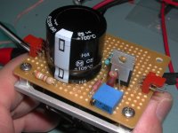

Yeah I tend to use perf board a lot, too. Been a LONG time since I tried making a PCB...they usually end up as expensive mistakes. Then again, doing it on a perf board can be really tedious too....
Wow, that's some serious wiring!
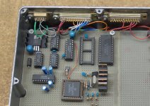
I have been using that construction method for a very long time. It is especially good for digital projects.
I still have the boards I made for a music synthesizer that I designed and built in 1970 / 1971 (yeah it took that long). It used a master oscillator and 12 seperate dividers to generate the top octave, and then several dozen flip flops to generate the lower octaves. More dividers and opamp summers allowed individual control of the harmonics present in the tone. The whole thing was fully polyphonic. This was long before Mostek was even a company, and the MK50240 wasn't even a dream. The tone generators took up 5 boards about 5 X 7 inches using RTL logic (before CMOS or TTL was popular) The linear power supply was 3.6 volts at 25 amps using germanium power transistors. The boards are in a box in my warehouse, the big stuff is long gone.
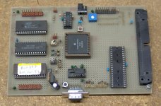
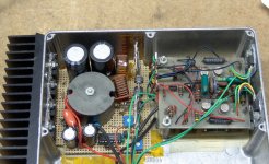
These are two newer projects that were in my closet. The boards in the Hammond die cast box make up an electronic fuel injection controller that I built in college, around 1991. Yeah I didn't start college until I was 37. It succesfully ran the engine in my turbo Dodge, and was responsible for the melting of at least one head gasket. It was abandoned after I totally aced the digital design class, and learned to hack the Shelby controller (made by Motorola). The other board is an EVB that I designed for the 68HC11F1. Noboby made what I wanted, so I made my own.
I still have the boards I made for a music synthesizer that I designed and built in 1970 / 1971 (yeah it took that long). It used a master oscillator and 12 seperate dividers to generate the top octave, and then several dozen flip flops to generate the lower octaves. More dividers and opamp summers allowed individual control of the harmonics present in the tone. The whole thing was fully polyphonic. This was long before Mostek was even a company, and the MK50240 wasn't even a dream. The tone generators took up 5 boards about 5 X 7 inches using RTL logic (before CMOS or TTL was popular) The linear power supply was 3.6 volts at 25 amps using germanium power transistors. The boards are in a box in my warehouse, the big stuff is long gone.
These are two newer projects that were in my closet. The boards in the Hammond die cast box make up an electronic fuel injection controller that I built in college, around 1991. Yeah I didn't start college until I was 37. It succesfully ran the engine in my turbo Dodge, and was responsible for the melting of at least one head gasket. It was abandoned after I totally aced the digital design class, and learned to hack the Shelby controller (made by Motorola). The other board is an EVB that I designed for the 68HC11F1. Noboby made what I wanted, so I made my own.
Attachments
Very cool, George. I also have a Turbo Dodge controller/logging module that I built to fulfill a similar need, but I never finished it because we can tune the stock modules so easily now.
Meet Master Blaster, or at least what's left of him. Back in school we had an analog design class. The same teacher that asked for a simple digital project (I did the EFI controller) asked the class to design and build a simple analog project (tubes were unacceptable antiques). He got each one of us to stand up in front of the class, state what our project was, state the goals, and state the measurement criteria. I simply replied that I was going to build a car stereo amp, and the teachers head would hit the roof of my car when I set it off!
The design was simple by todays standards, but way above the norm for students seeking a computer engineering degree, where analog meant the opamp in front of an A/D converter.
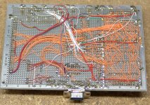
A push pull SMPS boosts the 12 volts to +/- 30 volts. That is the supply for 4 identical amplifier boards that make about 30 watts each and a subwoofer amp (BTL) that made about 100 watts. The power supply was done using this perf board construction, but the amps were on PC boards that I made. Some old timers may recognize them. They are one of the Tiger series, the Plastic Tiger, I think. The sub amp used two of the same boards but TO-3 output devices for more current capability and the load wired across the two outputs. The amp has been robbed for the sub amp and 2 of the main amps. Hey it has been in my closet for almost 20 years.
The little Dodge Omni had 2 6X9's 2 6 inch, and a 15 inch sub. The whole class gathered in the parking lot, and I put in a CD that was dead quiet until the bass drum hit. It took about 3 milliseconds for the teacher to jump out of the car screaming profanity, and I got my A.
I also did an autonomous robot for an IEEE competition for that school. It used two 68HC11 chips all wired on perf board like those seen here. No photos though, digital cameras werent invented then.
The design was simple by todays standards, but way above the norm for students seeking a computer engineering degree, where analog meant the opamp in front of an A/D converter.
A push pull SMPS boosts the 12 volts to +/- 30 volts. That is the supply for 4 identical amplifier boards that make about 30 watts each and a subwoofer amp (BTL) that made about 100 watts. The power supply was done using this perf board construction, but the amps were on PC boards that I made. Some old timers may recognize them. They are one of the Tiger series, the Plastic Tiger, I think. The sub amp used two of the same boards but TO-3 output devices for more current capability and the load wired across the two outputs. The amp has been robbed for the sub amp and 2 of the main amps. Hey it has been in my closet for almost 20 years.
The little Dodge Omni had 2 6X9's 2 6 inch, and a 15 inch sub. The whole class gathered in the parking lot, and I put in a CD that was dead quiet until the bass drum hit. It took about 3 milliseconds for the teacher to jump out of the car screaming profanity, and I got my A.
I also did an autonomous robot for an IEEE competition for that school. It used two 68HC11 chips all wired on perf board like those seen here. No photos though, digital cameras werent invented then.
Attachments
we can tune the stock modules so easily now.
Not sure which controller your cars use. In my cars there were two boxes. The "logic module" was inside the car. It ran a 6802 processor and used a masked ROM. It was a simple matter to install a socket for an EPROM. The "power module" was in the engine compartment. It contained the injector and coil drivers and the voltage regulator. Both were made by Motorola SPS. I found someone that sent me the schematics, but reverse engineering and dissasembling the code was the hard part. The Shelby Performance center sold a logic module that allowed higher boost and moved the rev limiter to 7200. I bought one and did a compare on its PROM and the Stock PROM. A few head gaskets later I had found the ormula for smoking Mustangs.
Shortly after this Chrysler started making their own controllers SMEC and SBEC are Chrysler built designs.
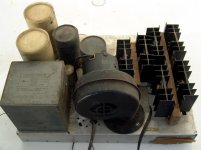
OK, now everybody knows that Tubelab has designed amplifiers from the "dark side" of the force, or should I say sandy side? I have a few more including a 400 watt monster that I built in high school! I recently dismantled it, saving the heat sinks. I did take pictures. I hit 1200 watts in 1971, but that was because of a lucky surplus find. Since there was no power transformer, we can't talk about it here.
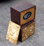
Photos, the 400 watt SS amp that I built in high school (1969) and a pair Of Speakers that I made. These are obviously old, pre disco even!
Attachments
Not sure which controller your cars use...
The 86 Turbo Z uses the LM/PM setup, but I converted it to 87 LM/PM because that logic module is a bit more sophisticated and the EPROM is larger (16kx8). It also has the SMEC harness spliced-in so that I can quickly switch to the SMEC for testing (I do some cals for local folks). The 87 CSX is still the stock LM/PM with a custom cal, 3 bar MAP, big injectors, etc, etc. They each have different cals with rather different origins. The CSX is a very early reverse-engineered calibration that has a lot of bugs but runs well at WOT where it counts. The Daytona's cal is more refined, but still has a few winter idle issues.[/QUOTE]
Since there was no power transformer, we can't talk about it here.
Hmmm...sounds like my dad's 8417 amp. He built it in the late 60s I imagine and gave me the amp a few years ago. It had only a small transformer for the preamp side but it did come with a wooden box filled with big capacitors and diodes and an unpolarized plug at one end....
- Home
- Amplifiers
- Tubes / Valves
- Mullard 5-20 KT88 PP blocks!