You probably have open resistors or defective transistors in the circuit driving this transistor.
Im going to check the circuit and go get some resistors / transistors if needed...
will post results later..
will post results later..
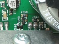
Do you have another pic of the area around FET401 Its right next to
Fet192..
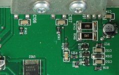
Also a pic of the other side of the board around the rectifiers ?
Someone has worked on this before and wanna make sure they are the correct parts that are in it..
Fet 192 and Fet401 are 540's correct?
Fet192..
Also a pic of the other side of the board around the rectifiers ?
Someone has worked on this before and wanna make sure they are the correct parts that are in it..
Fet 192 and Fet401 are 540's correct?
In the amp i have Fet191 has a diode solerd to leg 3 is that suppose to be there or did someone add it ?
Wondering if i should ake it out or not ?
Wondering if i should ake it out or not ?
Ok will do..
Hopefully all the right parts are in this amp someone has worked on this before and has been all over the board..
The amp i have here Fet192 Fet401 Fet191 all have IRF540's in there locations..
Also i rebuilt the area around Fet192 Replaced all resistors transistors and the regulator..
As soon as i powerd it on the fans spun for 1 sec then Q109,Q111,D105,Q108 all failed again..
Ok finally got the parts in for this amp..
I now have + - 15 volts on the op-amps..
Now i have 81 volts of DC measured directly across the speaker terminals..
All outputs test fine..
Any ideas where to go next?
I now have + - 15 volts on the op-amps..
Now i have 81 volts of DC measured directly across the speaker terminals..
All outputs test fine..
Any ideas where to go next?
Ok i found Q405 to be defective..
I cant read the numbers off it.
Wondering if u have a pic of the board around the op-amps or do you know what Q405 is suppose to be ?
I cant read the numbers off it.
Wondering if u have a pic of the board around the op-amps or do you know what Q405 is suppose to be ?
Q405 =C1URA I believe it is a jfet that mutes the input of both A3120's.Pin 1&3 on Q405 go to pins 2&3 on the A3120's. Pin 2 of Q405 goes to R421.
Q405 is marked C1U5A in this amp..
Cant find a data sheet on it but heres the reading i get
Top pin to left bottom pin :OL
Top pin to bottom right pin:OL
Left bottom pin to right bottom pin:0.015
Probes reversed
Top pin to bottom left:0.644
Top to bottom right:0.622
Bottom left to bottom right:0.015
Defective ??
Cant find a data sheet on it but heres the reading i get
Top pin to left bottom pin :OL
Top pin to bottom right pin:OL
Left bottom pin to right bottom pin:0.015
Probes reversed
Top pin to bottom left:0.644
Top to bottom right:0.622
Bottom left to bottom right:0.015
Defective ??
I THINK that part is OK.I have 3 of these amps here with blown power supply's and thats the same reading I get on all of them for Q405.They also test at about 25 ohms on pins 1&3.
And yes one of them I have is also marked C1U5A.
Does R417 test good?
And yes one of them I have is also marked C1U5A.
Does R417 test good?
That transistor is a JFET. That's normal.
Post the DC voltage on all pins of the two op-amps near the opto-couplers.
Also post the DC voltage across the power supply pins (5 and 8) for the two opto-couplers.
Leave the preamp board disconnected.
Post the DC voltage on all pins of the two op-amps near the opto-couplers.
Also post the DC voltage across the power supply pins (5 and 8) for the two opto-couplers.
Leave the preamp board disconnected.
Ok i found C401 with a leg broken off the board..
Its marked 100 25A
Is that a 100uf 25 volt cap?
Its marked 100 25A
Is that a 100uf 25 volt cap?
The voltages on the 2 op-amps are
Pin 1:-6.46
Pin 2:-13.32
Pin 3:-13.25
Pin 4:-14.95
Pin 5:-6.75
Pin 6:-79.8
Pin 7:-7.62
Pin 8:15.74
Pin 1:15.47
Pin 2:14.03
Pin 3:14.39
Pin 4:-14.39
Pin 5:14.52
Pin 6:14.01
Pin 7:14.96
Pin 8:15.93
Voltage across opto-couplers
Pin 5 to 8:18.04
Pin 5 to 8:15.99
If i use ground terminal as reference for the opto-couplers i get
Pin 5:4.16
Pin 8:-63.1
Pin 5:-81.2
Pin 8:-65.3
I notice something in the power supply cycling i can hear a small squeak .. When amp is powerd up i get 81 volts across the output terminals ...
If i leave the amp idle for a lil while once i hear the squeak the voltage will drop to 4.25 volts across the outputs for a few secs the it will go back up to 81 volts..
The amp does this over and over
Last edited:
- Status
- Not open for further replies.
- Home
- General Interest
- Car Audio
- MTX Thunder 81001