All the 470uf 63v caps vented in this amp also..
What causes this ??
Is it rca jacks came in contact with power wire or something else?
What causes this ??
Is it rca jacks came in contact with power wire or something else?
Too low of a load impedance, shorted output filter inductor, possibly something causing the output stage to operate at the wrong frequency...
Ok replaced the caps,gte resistors,drivers,power supply fets..
Amp will not power up..
Heres what i get on the 494
Pin 1:0.00
Pin 2:4.75
Pin 3:0.06
Pin 4:1..15
Pin 5:1.50
Pin 6:3.34
Pin 7:0.00
Pin 8:0.64
Pin 9:0.00
Pin 10:0.00
Pin 11:1.11
Pin 12:13.26
Pin 13:4.95
Pin 14:4.95
Pin 15:4.95
Pin 16:0.00
Any ideas??
Amp will not power up..
Heres what i get on the 494
Pin 1:0.00
Pin 2:4.75
Pin 3:0.06
Pin 4:1..15
Pin 5:1.50
Pin 6:3.34
Pin 7:0.00
Pin 8:0.64
Pin 9:0.00
Pin 10:0.00
Pin 11:1.11
Pin 12:13.26
Pin 13:4.95
Pin 14:4.95
Pin 15:4.95
Pin 16:0.00
Any ideas??
Do you see any drive signal on the small driver transformer?
If there is absolutely no drive signal, re-check the DC voltage on pin 4 of the 494.
If there is absolutely no drive signal, re-check the DC voltage on pin 4 of the 494.
Not sure but im thinking the 494 has failed.. Unless this is normal
If i place black probe on pin 8 and red probe on Pins 9,10,11,12 i get 23.4 ohms between the pins is this noraml or is it defective?
If i place black probe on pin 8 and red probe on Pins 9,10,11,12 i get 23.4 ohms between the pins is this noraml or is it defective?
No
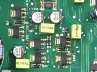
R625,R626 burn up ..
Q625,Q626 A56's have been replaced also and are defective also..
Someone has been inside this amp before..
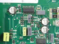
Do you happen to have a pic of the area around the 494 and right behind it all thoose transistors have been messed with and dont look right to me
R625,R626 burn up ..
Q625,Q626 A56's have been replaced also and are defective also..
Someone has been inside this amp before..
Do you happen to have a pic of the area around the 494 and right behind it all thoose transistors have been messed with and dont look right to me
The A56's and 06's That sit by the rail caps there are 6 of them total that al sit right next to eachother in the middle of the board
See attached.
If you don't find any other faults, replace the A56s and resistors, remove the driver transformer and connect a 1k ohm resistor from the center tap of it to each of the outer windings (all of this on the side of the transformer connected to the A56s).
To make sure that the power supply FETs remain off, connect 1k resistors to the other side of the driver transformer as well (same configuration).
Do you see a drive signal on the outer legs of the driver transformer connected to the A56s?
Attachments
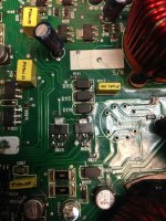
Leave the FETs out for now.
Since the FETs are out, all you need to do is install two resistors. Looking at the bottom 4 pads with the left-most #1 and the right-most #4, solder one resistor from 1-2. The other resistor will connect between 3 and 4.
Since the FETs are out, all you need to do is install two resistors. Looking at the bottom 4 pads with the left-most #1 and the right-most #4, solder one resistor from 1-2. The other resistor will connect between 3 and 4.
- Status
- Not open for further replies.
- Home
- General Interest
- Car Audio
- MTX Thunder 801D