I have an older version of this amp .
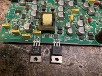
I’m going to to use the 3205’s in the power supply section .
Does anyone know the value of the 2 gate resistors R436,R435 ?
And wondering what outputs I can use in this since I can’t find the originals the originals are IRFB42N20D
I’m going to to use the 3205’s in the power supply section .
Does anyone know the value of the 2 gate resistors R436,R435 ?
And wondering what outputs I can use in this since I can’t find the originals the originals are IRFB42N20D
The gate resistors are 39.2 ohms.
The outputs are readily available.
IRFB42N20DPBF Infineon - MOSFETs - Distributors, Price Comparison, and Datasheets | Octopart component search
The outputs are readily available.
IRFB42N20DPBF Infineon - MOSFETs - Distributors, Price Comparison, and Datasheets | Octopart component search
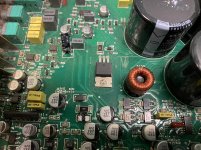
D198 likely burned when the amp lost ground and tried to ground through the RCA shields.
Those FETs will work.
Those FETs will work.
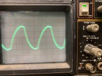
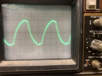
I took the class D chip out and jumped pins 1 to 8 with a 1k resistor
When adjusting the gain the test speaker still has excessive movement and bounces back and fourth a lot .
Could this be from a bad gain pot ?
When adjusting the gain the test speaker still has excessive movement and bounces back and fourth a lot .
Could this be from a bad gain pot ?
Class D chip? U141 is a VCA (Voltage Controlled Amplifier). It has nothing to do with class D amplifiers.
Is the 1k resistor between D198 and D199 within tolerance?
Are you using a signal source with a grounded shield?
Are the RCA shields securely connected to the RCA jack frame?
Side note, leave the burned diode out of the circuit.
Is the 1k resistor between D198 and D199 within tolerance?
Are you using a signal source with a grounded shield?
Are the RCA shields securely connected to the RCA jack frame?
Side note, leave the burned diode out of the circuit.
My mistake calling it a class d chip .
The resistor measures within tolorance .
The rca jacks are securely connected to the frame
The resistor measures within tolorance .
The rca jacks are securely connected to the frame
What is the greatest voltage you read on the output pins of any of the op-amps in the preamp section?
Try with the black probe on the RCA shields and also on the primary ground.
Try with the black probe on the RCA shields and also on the primary ground.
If I use main ground terminal I get 0.53 volts on pins 1,7 of the TL072’s
If I use rca ground I get 0 volts
If I use main ground on pins 1,7 of the NE5532’s I get 15.41 volts
If I use rca ground on pins 1,7 of the NE5532’s I get -14.86 volts
I have +- 16 volts on the supply pins for the opamps
If I use rca ground I get 0 volts
If I use main ground on pins 1,7 of the NE5532’s I get 15.41 volts
If I use rca ground on pins 1,7 of the NE5532’s I get -14.86 volts
I have +- 16 volts on the supply pins for the opamps
0.52 volts
I noticed the optocouplers have different voltages on the the voltages don’t match from 1 to the other is this normal or should I post the voltages ?
I noticed the optocouplers have different voltages on the the voltages don’t match from 1 to the other is this normal or should I post the voltages ?
My mistake if I use main ground on the NE5532 I get -14.85 volts
If I use rca ground I get -15.41 volts but only on 1 5532
All of the other opamps read the same no matter what ground I use the most voltage I get is 0.54 volts on pins 1,7 of all opamps .
I think the problem is with the optocouplers.
Here is the voltage on both of them
Pin 1:0.00
Pin 2:-0.06
Pin 3:0.00
Pin 4:0.00
Pin 5:0.01
Pin 6:6.87
Pin 7:7.04
Pin 8:19.26
Pin 1:0.00
Pin 2:0.00
Pin 3:0.00
Pin 4:0.00
Pin 5:-78.4
Pin 6:-70.4
Pin 7:-70.4
Pin 8:-58.0
Does the amp produce audio?
What's the circuit board designation of the 5532 with -15v on its output?
What's the circuit board designation of the 5532 with -15v on its output?

- Home
- General Interest
- Car Audio
- MTX Thunder 1501D