This amp had me scratching my head for a while because the bicolor status LED would only glow faintly on both sides with remote applied after I replaced all the FETs, but as it turns out it’s actually making both rails and has good output drive. Guess the lamp circuit needs work, but my question is:
Is it normal for these to change the PS wave shortly after startup?
When I first apply remote I get pic #1, after a couple seconds it changes to #2 which to me looks terrible but the amp seems to function this way and nothing gets hot.
Is it normal for these to change the PS wave shortly after startup?
When I first apply remote I get pic #1, after a couple seconds it changes to #2 which to me looks terrible but the amp seems to function this way and nothing gets hot.
Attachments
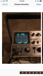
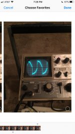
It acts like it has a regulated supply. Reduce your 12v supply voltage to see if the waveform changes to something more like you'd expect to see.
Sure enough, it flattened out around 10v input then goes all lopsided if I advance it past 11.5 or so. Guessing it’s working as advertised, if that’s the case I’m gonna move on to why this LED isn’t behaving.
Turns out the bicolor lamp was burned out or something, not a circuit fault. I put individual red and green ones in and they work fine, but now a new problem: they are both on at the same time.
The way this is supposed to work is with the remote on the red LED is supposed to glow, if a fault condition occurs the green side of the bicolor is supposed to come on as well which is meant to give a ‘yellow’ fault indication on the front panel. I don’t like red for OK and green for not OK and you could clearly see each side of the bicolor through the totally clear lens anyway which is ambiguous AF, so I’m gonna swap them to calm down my OCD cause it seems backwards to me. So it will be a green ‘on’ light and if anything bad happens, the red ‘fault’ light will come on.
Question now is: why is the fault light on if the amp is working?
The fault lamp is driven my pin 14 of an LM339 comparator, anyone know what is has for input? Obviously it has temp sensing, but I don’t have a diagram so I don’t know what else could cause it to come on and tracing would be a nightmare due to the rampant use of vias and traces all over the bottom of this board.
If you have the tutorial, there is a generic control circuit on the MTX 7801 page.
Are the inputs to the 339 right for both LEDs to be on?
Are the inputs to the 339 right for both LEDs to be on?
Inv input for the corresponding section is referenced to 2.5v, non inv is at 4.85v so it should be outputting Vcc (13v), but the output pin is only making 5v so I think the comparator may be shot. The way the bicolor is driven the center pin always gets Vcc when the remote is on, the ‘on’ lamp goes straight to ground so it always lights along with the remote. The protect lamp goes to comparator pin 14 (output), so I would think if the comparator were outputting Vcc like it’s supposed to the protect lamp would see Vcc on both pins and not be lit up. In other words comparator output high=lamp off, unless I’m not understanding the circuit correctly.
The comparator is not an op-amp, it has an open collector output. The output can only pull down and has to be pulled up by an external source, and it's likely being pulled up to 5v.
Then this circuit makes no sense, how is the protect lamp ever supposed to turn off if it can’t source voltage? Maybe the pull-up is supposed to be 12v and something is wrong in that respect?
I don’t think so, this appears to be a common anode lamp meaning the cathodes each need to see lower than input (remote) voltage in order to turn on. One side gets constant ground through a dropping resistor (the on lamp), the protect lamp is supposed to get a ground via the comparator. I don’t see how this could possibly work otherwise.
You are correct that the comparator output is pulled to 5v, but when the LED is in the circuit it forward biases which raises the voltage at the comparator output to around 10v. This happens because the LED is supplied with remote voltage, so the comparator output sees B+(-Vfwd of the lamp). If I remove the lamp, comparator output stays pegged to 5v (as it should).
In other words the only thing accomplished by the comparator changing to a low state would presumably be that the protect lamp gets brighter???
Not a clue, I have no idea what MTX were thinking when they designed this thing.
Verified by shorting the comparator inputs together, the lamp gets blazing bright and the PS shuts down. I think what I’m going to have to do is supply the protect LED from the 5v regulator instead of where it is now, that’s the only thing that makes sense.
Easy fix I guess, I just moved the wire for the center leg of the LED from where it originally was to a 5v source and now it works like I’d expect. At first application of remote both lights illuminate, then PS boots, then the red light goes out as the output stage begins switching. From there only the green ‘on’ light will be illuminated, unless the fault circuit is triggered. I drilled another hole in the case for the new light, everything get reassembled tonight after I install the new output stage devices. I don’t anticipate any issues.
There's no 10v supply, if you're referring to the 10v I mentioned previously- that appeared at the comparator because the LED forward biased, which caused it to jump up to 10v at comparator output instead of the 5v it's normally supplied with.
If I had to guess I think the lights were supposed to get 5v all along, it's possible the circuit supplying that voltage had something wrong with it and I just missed it but either way it's working now. I can't find anything else wrong with it and it makes clean audio, so I'm calling it done that way it is.
If I had to guess I think the lights were supposed to get 5v all along, it's possible the circuit supplying that voltage had something wrong with it and I just missed it but either way it's working now. I can't find anything else wrong with it and it makes clean audio, so I'm calling it done that way it is.
- Home
- General Interest
- Car Audio
- MTX RT1000D Odd Drive Wave