I have gone through the driver board. I replaced the two burned resistors, but found no other fault.
I have 10 of 14 original outputs. For testing purposes, will it be ok to operate the amp on only the ten before I install all new outputs?
I have 10 of 14 original outputs. For testing purposes, will it be ok to operate the amp on only the ten before I install all new outputs?
You can test it with 10. If you try to play it normally with the lowest rated load impedance, it's likely to fail.
This amp now shows more signs of life, but it still isn't right yet.
With my resistor in line with B+ it will power up and the fans are now on which they were not before. I measure ~5.5VDC across the speaker terminal and if you connect a speaker to it, you can hear fan noise through the speaker, no audio is finding its way there. I draws ~2.5A with resistor in line. If I remove the resistor the amp draws ~20 amps just before I shut it down. I am sure it would draw more if I let it.
I do not see rail to rail oscillation. I have verified the gate resistors are good on the outputs. My meter does not read low enough to verify the emitter resistors, none of them look like they have overheated. I verified the large jumper wires are making their point to point connections.
What is my next step?
The problem is almost certainly on the driver board. Start lifting the smaller transistors and testing them carefully. If not have open junctions and none are leaky, you'll have to check the larger transistors after you've removed them from the board.
Whatever is wrong on the audio driver board is still elusive.
I have checked everything except the two ICs and the SMT capacitors.
Point to point everything is connected. The SMT resistors measure right on or close to expected in circuit. I have particularly zeroed in on two of the large SMT A42's and the surrounding area since they appear to drive the outputs.
I this point I have replaced ALL of the transistors on the board one at a time to make sure I didn't make an error, and it still has the same problem. I have checked and re-checked the connections after the replacements, and resistances, etc.
What are the chances either of the ICs failed?
I open to further advice on this one.
Email me. I have a sony schematic diagram that may be close. You'll have to make a list of the corresponding components on your board so I can get an idea of the layout in your amp.
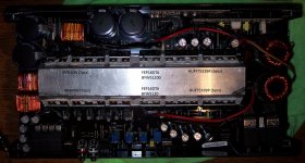
MTX main board
HUF75339P Power supply MOSFETs there are twelve, six per side.
FEP16DTA rectifier, there are two, one per side.
BYW51200 rectifier, there are two, one per side.
TIP29C, only one
TIP30C, only one
LM337T, only one
LM317T, only one
IRF640N Output MOSFETs there are fourteen, seven per side.
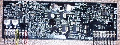
The top set of 640N's gate resistors connect to driver board pins circled in yellow.
The bottom set of 640N's gate resistors connect to driver board pins circled in red.
Audio Driver Board
MPSA92 two
PZTA42 four originally marked as P1D
MMBTA42 one originally marked as 1D
MMBTA06 three originally marked as 1GM
MMBTA56 three originally marked as 2GM
MMBTA92 two originally marked as 2D
MMBTA5401 one originally marked as 2L
BAV99 three originally marked as A7
MMSZ5233 one originally marked as E3E
U102 marked LM311
U100 marked D72C & EZ651 made by ST Microelectronics
HUF75339P Power supply MOSFETs there are twelve, six per side.
FEP16DTA rectifier, there are two, one per side.
BYW51200 rectifier, there are two, one per side.
TIP29C, only one
TIP30C, only one
LM337T, only one
LM317T, only one
IRF640N Output MOSFETs there are fourteen, seven per side.
The top set of 640N's gate resistors connect to driver board pins circled in yellow.
The bottom set of 640N's gate resistors connect to driver board pins circled in red.
Audio Driver Board
MPSA92 two
PZTA42 four originally marked as P1D
MMBTA42 one originally marked as 1D
MMBTA06 three originally marked as 1GM
MMBTA56 three originally marked as 2GM
MMBTA92 two originally marked as 2D
MMBTA5401 one originally marked as 2L
BAV99 three originally marked as A7
MMSZ5233 one originally marked as E3E
U102 marked LM311
U100 marked D72C & EZ651 made by ST Microelectronics
Attachments
I was referring to the transistors on the audio driver board.
Example:
Sony board >> MTX board
Q20 > Q?
Q21 > Q?
Example:
Sony board >> MTX board
Q20 > Q?
Q21 > Q?
I think the Sony schematic and the MTX are too dissimilar to make a useful list. I find very little connected the way the schematic shows.
Here is a partial list of components that apear most like their Sony counterpart.
Sony = MTX, component
Q17 = Q1, mmbta06
Q19 = Q3, mmbta92
Q20 = Q116, mpsa92
Q21 = Q114, mmbta56
Q22 = Q119, mpsa92
Q23 = Q123, pzta42
Q24 = N/A
Q25 = Q121, mmbta56
Q26 = N/A
Q27 = Q117, pzta42
Q28 = N/A
Q29 = Q118, mmbta56
Q30 = N/A
Q31 = Q115, mmbta92
Q32 = Q2, mmbta42
The rest don't apear to be connected in a similar way.
That makes it very similar. I'm going to use the numbers from the Sony diagram.
There is a resistor between collector of Q20 and the emitters of Q21 and Q22. What is the voltage across that resistor.
There is a resistor between collector of Q20 and the emitters of Q21 and Q22. What is the voltage across that resistor.
It would appear that one of the two originally burned resistors is one that connects between those two points (R140, 475 Ohm) and I read ~26.6VDC accross it.
It is still reading ~475 ohms measuring from one point away each direction to verify it is connected and circuit.
With 26+v across it, it's dissipating 1.4w. That should be enough to melt the solder on the resistor. If it's not getting hot, double-check the voltage. If it still has 26v across it and isn't getting hot, it's either open, out of tolerance or has a bad solder connection.
It absolutely IS getting that hot. I am only leaving the amp on long enough to take that measurement and then shutting it off.
- Home
- General Interest
- Car Audio
- MTX JH1200