I found that two IRF640N outputs (FET404 & FET6) were shorted, one on each side. I removed all fourteen to find the two, checking each one. None of the remaining twelve appear to be leaking. The TIP29C & TIP30C were checked in circuit, and are not shorted. All of the 10 Ohm gate resistors are ok. I presume the .1 Ohm, 5W resistors are ok, none are even remotely discolored.
I re-installed all of the IRF640Ns that appear ok and left out the two shorted ones at those above FET locations. The amp draws excessive current. I removed the four rectifiers and the amp idles at ~2A draw. Is that high for an unloaded power supply?
Does this amp require all fourteen of the outputs to be good and installed or are there more areas I need to look at?
Did you check the components on the driver board? They often fail when the outputs fail.
I would expect the amp to work with one transistor missing from each side.
2A is high but doesn't necessarily mean that there is a problem.
I would expect the amp to work with one transistor missing from each side.
2A is high but doesn't necessarily mean that there is a problem.
I checked the A92s and A42s in circuit and they are not shorted.
Should I check the smaller components?
Should I check the smaller components?
How much was the excessive current draw?
Did it draw excessive current as soon as remote voltage was applied?
Did it draw excessive current as soon as remote voltage was applied?
It does blow a 25A fuse shortly (~1.5 seconds) after remote voltage is applied. Once the draw begins, it climbs rapidly. I think it was close to ~30A when fuse blew.
With a limiting resistor in line with B+, the amp cycles on and off because the voltage drops too low for the amp to stay on but it does not blow a 15A fuse this way.
With a limiting resistor in line with B+, the amp cycles on and off because the voltage drops too low for the amp to stay on but it does not blow a 15A fuse this way.
When it's cycling on and off, do you see rail to rail oscillation on any legs of the output transistors?
I re-installed the rectifiers.
With my 3 Ohm resistor and a 15A fuse in line with B+ the power light comes on with ~4 amp draw, however the voltage at the amp's terminals is ~8.5VDC and does not change much as I adjust my power supply from 12V-16V.
Testing any of the three legs of the output located at FET18 shows nothing on the scope.
I did, but I have been fooled before, and I find it hard to believe that more are not damaged than just the two shorted ones.
It wouldn't be a problem to remove them all again to check them all again.
While all the outputs are removed, is there any testing I should do to confirm the driver board is operating correctly?
It wouldn't be a problem to remove them all again to check them all again.
While all the outputs are removed, is there any testing I should do to confirm the driver board is operating correctly?
I removed all of them again and found two more that are NOT ok one from each side again. I am down to ten total that appear to be OK.
When I reinstalled them after the first check, I did not take care to ensure they went back into the same location they came out of.
Would that have mattered?
When I reinstalled them after the first check, I did not take care to ensure they went back into the same location they came out of.
Would that have mattered?
It wouldn't matter if you reinstalled them in different locations if they're all the same part number.
Some people only check to see if transistors are shorted. Did you also confirm that none were leaking?
Some people only check to see if transistors are shorted. Did you also confirm that none were leaking?
Before checking each one all three pins were shorted together.
Of the ten remaining FETs this is how I just checked them,
Black probe on drain, no continuity between gate and drain.
Black probe on gate, no continuity between gate and source.
Black Probe on drain, ~1-2MOhms between drain and source.
Repeating each step with probe position reversed yielded no continuity in all three positions.
That should have found any defective FETs although it's possible another one has been damaged if there is a problem on the driver board.
It's possible that the outputs failed due to a fault on the driver board.
If...
the outputs are not defective
there are no defective insulators under the transistors
there are no bad connections between the gate legs and the resistors
the gate resistors are within tolerance
The problem is almost certainly on the driver board. You may need to check virtually every component on the driver board. They generally have, at least, a very slight discoloration. A high power lighted magnifying glass can sometimes help you find defective components quickly.
If this is a single-sided board, you should also check for bad connections. I've found several on the larger wires.
I have removed the driver board.
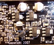
I found that R142 and R140 are out of specification. Both are visibly burned and I can not read R140's value. I believe that they are both the same value of 475 Ohms. My picture makes R140 look like the last digit is a 1, but under magnification, it is clearly a 0.
R140 connects to the emitter of Q114, the transistor marked 2GM.
R142 connects to the emitter of Q3, the transistor marked 2D.
The two resistors are the only faults I could find on the board. None of the semiconductors show shorted in circuit.
Can you confirm those two resistors are in fact 475 Ohm?
Attachments
Thank you Perry.
In your experience, would you agree that it is possible those two resistors are the only defects on the driver board or is there something I should remove to examine closer?
In your experience, would you agree that it is possible those two resistors are the only defects on the driver board or is there something I should remove to examine closer?
It's unlikely that they would have failed alone. You need to check all of the transistors in that area for leakage and open junctions as well as shorts.
- Home
- General Interest
- Car Audio
- MTX JH1200