Maybe I posted my amp problem in the wrong forum. Anyway, I have a 421D that has roughly 40VDC on the speaker output terminals. C143, C140 and C120 all showed signs of overvoltage. I have removed the output fets and still have full dc on the terminals. It looks as though the feedback protection circuit took a hit also. R110 and R107 look a bit burnt. A schematic would be very helpful, that seems impossible to come by.
Any ideas?
Any ideas?
Are you sure that there are no solder bridges between the solder pads for the FETs you removed?
If there are no solder bridges, the DC could simply be stored in the output filter capacitors. Have you tried connecting a load (high power resistor) across the speaker terminals to see if the voltage will come down? If you try this, have the rest of the power transistors clamped and have a 10 amp fuse in the B+ line to protect the power supply FETs.
If R107 is burned and is connected between pins 1 and 2 of the NE5532, the op-amp may be damaged.
Are those the 3 caps (the ones you listed) next to the speaker terminals?
Positive no solder bridges.
With a 8ohm load I have 187mV on the speaker terminals, and the power supply is drawing less than 1 amp.
R107 reads about 3K, R110 is open. Any idea what value that should be. R110 is burned bad enough the value isn't legible.
The 3 caps are by the speaker terminals, they seem to go in a series config (+-+--+). The two outer pos. one attaches to speaker + and the other to speaker -.
I get 43Vdc +- for rail voltage, power supply seems fine. Maybe the output caps took a hit when a fet failed and that also took out the feedback portion.
Thanks,
Cory
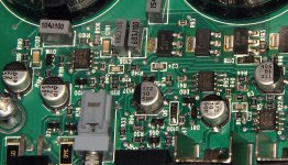
I'm not sure what those resistors are in that amp. In the 6500D (which should be very similar), R110 is a 12.7k. R107 is a 3.32k. Look at the adjacent resistors in the attached image (view full size so that it will be as sharp as possible) to see if the rest of the resistors match those in the photo. If so, R110 and R107 are likely the same.
Search the car audio forum for MTX 6500D threads. They should answer a lot of questions. The repair procedure will essentially be the same.
Search the car audio forum for MTX 6500D threads. They should answer a lot of questions. The repair procedure will essentially be the same.
Attachments
Circuit looks the same, surrounding parts match up also. I will replace those and the op-amp, it was getting very warm while it was powered up.
Thanks for the help.
Thanks for the help.
the power supply seems to be running cool, nothing out of the ordinary for a switcher.
Is that op-amp used for shutdown protection? It seems to take a reading from the pos speaker terminal.
Is that op-amp used for shutdown protection? It seems to take a reading from the pos speaker terminal.
That op-amp is used as a buffer and a differential amp. R110 is a resistor in the feedback line from the output.
The LM311 near FET191 is for over-current protection.
I misunderstood the previous post. The NE5532 op-amp was getting hot. They run hotter than many other op-amps but if it's significantly hotter than the other NE5532s, it may well be defective.
The LM311 near FET191 is for over-current protection.
I misunderstood the previous post. The NE5532 op-amp was getting hot. They run hotter than many other op-amps but if it's significantly hotter than the other NE5532s, it may well be defective.
The 5532 and both resistors are replaced now and running much cooler.
I have put two of the fets back in, so I have output capability on a lower current level. I have noticed the gate signal on Fet101 is running way high,
80V pk-pk squarewave. Fet191 has a nice 10Vpk-pk waveform, these were referenced to gnd. A schematic of this portion would be nice, hard to figure out what they are using to drive the gate.
Both banks of FETs have a drive signal of ~10v p-p. The one that's tied to the negative rail looks like a 10v signal. The high-side FET is a follower so the source swings to the upper rail. The gate drive signal swings about 10v over the rail. The Vgs of the high-side FET never exceeds the 20v that the FET's designed to handle.
Email me. I have a sony schematic that uses a similar design.
Email me. I have a sony schematic that uses a similar design.
The Vgs probably isn't high. When the gate is 10v above the rail, the source is at the rail so the Vgs is only 10v.
I sent the service manual.
I sent the service manual.
So I have what seems to be nice square wave osc. on the source of FET101 and the drain of FET191. Measure about 80Vpk-pk roughly 64Khz.
I get very little amplitude when running a 1Khz sine into the inputs. I can vary the amplitude without any change in the output. Should I be looking at the LM339?
I get very little amplitude when running a 1Khz sine into the inputs. I can vary the amplitude without any change in the output. Should I be looking at the LM339?
Good point on the 1KHz not making it through the cross over.
The guy that suggested a 1KHz test signal probably forgot this is a sub
amp!
The guy that suggested a 1KHz test signal probably forgot this is a sub
amp!
Thanks Perry for the help, the amp is functioning. I only have one set of output fets in place right now but that is enough to hear some sound from it.
Amazing what happens when the correct freq gets through!!
So to sum up the issue: Bought from ebay known bad, output caps burst, one fet shorted and the NE5532 that gets feedback or feeds signal to output was damaged. It also had a couple SM resistors burned in that circuit.
That is 3 amps repaired this week, 1 punch 60DSM, 1 Pioneer GM-X502, 1 MTX 421D.
Thanks,
Cory
Dear Brandes.cm:
I suggest to you acquire the Perrys tutorial repair amp.
“The information provided in this tutorial will help you to avoid making the most common mistakes and will greatly increase your chances of success”
http://www.bcae1.com/repairtutorialcdinfo.htm
I suggest to you acquire the Perrys tutorial repair amp.
“The information provided in this tutorial will help you to avoid making the most common mistakes and will greatly increase your chances of success”
http://www.bcae1.com/repairtutorialcdinfo.htm
- Status
- Not open for further replies.
- Home
- General Interest
- Car Audio
- MTX 421D issues