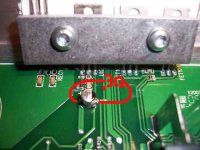
It's a capacitor. The amplifier will work without it.
Is C118 swollen?
Is D102 cracked?
What blew black soot onto the board? Is U102 blown (visibly)?
Are you sure you don't have any solder bridges between any of the legs of the FETs or the rectifier pads?
Is C118 swollen?
Is D102 cracked?
What blew black soot onto the board? Is U102 blown (visibly)?
Are you sure you don't have any solder bridges between any of the legs of the FETs or the rectifier pads?
i double and triple checked for bad solder and i cant find anything visiably or with my beeping continuity tester.
it looks like someone else tried swaping out the U102 you can see the so-so solder job on the legs of it. i suspect it failed and thats what caused the splatter.
the cap at C118 looks fine and has continuity across it and there is another on the other side of the heat sink, location C119 it has continuity aswell and looks the same.
and the piece at D102 looks fine.
when i put full voltage to it now, it just forces my power supply into shutting off. but it powers up with resisted power.
no if i do that the voltage drops even further now im down to 1.2v
should i send pictures of anything? should i put the transistors back in?
should i send pictures of anything? should i put the transistors back in?
Pull FET101-104.
Look at the gate drive signal on the FETs (all 4 of them). With your scope set to 10v/div and the timebase set to 10uS, do you see ~4 cycles and the signal swinging ~30vp-p?
If not, post a photo of the waveform you do have.
Look at the gate drive signal on the FETs (all 4 of them). With your scope set to 10v/div and the timebase set to 10uS, do you see ~4 cycles and the signal swinging ~30vp-p?
If not, post a photo of the waveform you do have.
i pulled both little caps and the main voltage is being drawn down still. after the caps are out they both measure at .01 ohms.
i am going to order parts for the other amps i am working on. should i order anything for this amp at the same time? how do i know what part number to use to replace the capacitor i put the picture of? its just really small and brown there arent any numbers on it
i am going to order parts for the other amps i am working on. should i order anything for this amp at the same time? how do i know what part number to use to replace the capacitor i put the picture of? its just really small and brown there arent any numbers on it
The amp will work without the brown SMD capacitor.
Check the large SMD diodes (particularly those designated RECxyz). Are any shorted?
I'd recommend ordering new regulators. They are likely directly connected to the shorted capacitors.
Check the large SMD diodes (particularly those designated RECxyz). Are any shorted?
I'd recommend ordering new regulators. They are likely directly connected to the shorted capacitors.
- Status
- Not open for further replies.
- Home
- General Interest
- Car Audio
- Mtx 3401