Post a photo of your board.
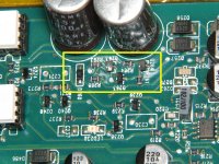
I did some closer looking and think i found the cap. Is this the one?

Voltage 5-8?
Now im getting frustrated.
I shorted out the cap as pictured with a jumper. Powered up the amp got a reading on pins 5 to 8 which showed 61v DC. Then the voltage began dropping. In about 4 seconds it came down to 51v and then the capacitor next to the 3120 exploded....
Last edited:
Are you thinking that something is faulty in the voltage regulator circuit supplying the optocoupler?
Yes.
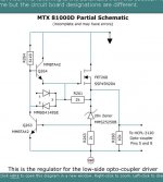
All of the components in the rectangle in the image below are suspect (expect to replace all of them). FET260 (may have survived), the opto-coupler and the cap will have to be replaced. There is a Zener that helps protect the gate of the output transistors that may have failed as well.
All of the components in the rectangle in the image below are suspect (expect to replace all of them). FET260 (may have survived), the opto-coupler and the cap will have to be replaced. There is a Zener that helps protect the gate of the output transistors that may have failed as well.
Attachments
Yes.
All of the components in the rectangle in the image below are suspect (expect to replace all of them). FET260 (may have survived), the opto-coupler and the cap will have to be replaced. There is a Zener that helps protect the gate of the output transistors that may have failed as well.
I am in process of ordering everything but wanted to double check what I'm ordering is correct.
1D (q263 and Q264) = MMBTA42TPMSCT-ND
J5 (D260) = MMSZ5250B-FDIDKR-ND
D42 (D263) = BZX84C3V0-FDICT-ND
R260 & R261are 2000ohm 1/8w
R263 is a 1000ohm 1/8w
R264 is a 61,900ohm 1/8w
Last edited:
See attached.
Thank you!!!! 🙂 🙂
However I noticed this amp is using a 42n20 for FET260 from mitek....was that one of the upgrades from the 81000d to the 1501d?
The FET isn't critical. Both are great overkill for a regulator that doesn't produce more than a few amps.
Did you have the heatsink mounted components tightly clamped down when everything blew out?
Did you have the heatsink mounted components tightly clamped down when everything blew out?
The FET isn't critical. Both are great overkill for a regulator that doesn't produce more than a few amps.
Did you have the heatsink mounted components tightly clamped down when everything blew out?
Only FET 260 and 471 as those tend to get hot quick. The rest were not and did not feel warm to the touch.
The FET isn't critical. Both are great overkill for a regulator that doesn't produce more than a few amps.
Did you have the heatsink mounted components tightly clamped down when everything blew out?
In process of changing everything in that voltage regulation circuit. I measured all resistors in circuit and out of circuit. Out of circuit all are within spec. HOWEVER when i changed out q263 and q264 with new replacements, the in circuit value of R264 changed from ~23k ohms to around 57k ohms!! (Dead cap and optocoupler are also out of circuit for this.)
EDIT: diode array appears to be fine but replacing regardless.
Can i power the amp up with the optocoupler and cap out of circuot to measure the supplied voltage to the optocouplers legs 5 to 8?
Last edited:
OK bigger update, flipped the board over to remove the power supply fets and saw that the trace connecting the drain of FET471 to a small transformer was burned. Ill upload a picture shortly. Does this provide any clues as to what happened?

Last edited:
Defective driver IC, FET and/or transformer.
Mosfet 471 checks out on my transistor tester when i pulled it. Now how do i test the transformer? Which IC drives fet 471?
"Which IC drives fet 471?"
It's the IC that's likely connected to the gate of the FET through one gate resistor.
It's the IC that's likely connected to the gate of the FET through one gate resistor.
"Which IC drives fet 471?"
It's the IC that's likely connected to the gate of the FET through one gate resistor.
LMAO!!! Yes of course, but I was hoping you knew right off the top of your head or had an amp schematic handy....lol
I had to abandon the amp for a little while and fix the wifey's pool pump and then off to work tomorrow with the covid19 patients. Will update with what else I find.
Thank you for all the help 🙂
Other than the driver IC for the main power supply, how many other driver ICs are there in the amp?
Other than the driver IC for the main power supply, how many other driver ICs are there in the amp?
Ok it appears that U450's #6(?) pin drives FET 471's gate leg. (See backlit photo - also i left the drain leg un-soldered at this point intentionally after testing the fet)

Also

Do diodes have to be tested out of circuit to definitively determine if they are bad? Im getting some bizzare readings from my DMM in diode setting. (D199 and D198 read the same 0.255v regardless of orientation of my probes vs the diode's anode and cathode)
Also removing fet 471 and powering up the amp i should have a fairly large square wave on the gate if U450 is operating properly?
The output of the IC is determined by the voltage on various terminals of the IC when it's in the circuit.
Did the FET short from the gate to either other terminal?
Why did the trace burn? The gate resistor should have opened before the trace burned?
Did the FET short from the gate to either other terminal?
Why did the trace burn? The gate resistor should have opened before the trace burned?
- Home
- General Interest
- Car Audio
- MTX 1501d (old design amp)