Well I couldn't help myself and picked up another toasted MTX 1501d. Replaced all the power supply FETs and 2 gate resistors and the power supply fires up without issue.
Oddly enough, there is no switching on any of the output fets. LED 238 is not illuminated. Going off of memory here, but one opto-coupler has zero significant voltage on any pins, and it there is negative rail voltage on pins 5 and 8 of the optocoupler nearest the edge of the board.
Thoughts on were I should start?
Did you measure the 5-8 voltage directly across those points?
Oops i did not. I made all measurements using amplifier main ground as ground.
Ill do that tomorrow morning when i get back in
Ok optocoupler closest to the edge of the board has 20.26v with black probe on pin 5 and red probe on pin 8.
The other has no voltage from pin 5 to 8.
VCC rides above negative rail in this amp correct?
The other has no voltage from pin 5 to 8.
VCC rides above negative rail in this amp correct?
Check the two 0.22 ohm resistors near the low-voltage transformer.
Do the op-amps have ±15v on their PS terminals?
Do the op-amps have ±15v on their PS terminals?
Check the two 0.22 ohm resistors near the low-voltage transformer.
Do the op-amps have ±15v on their PS terminals?
Both R220s measure less than 0.5ohm incircuit.
Hmm I do not believe I am getting VCC.
VCC?
Is that not the power supply on the pinouts? Vcc+ and vcc-?
So, are you saying that you have no voltage on the power supply pins of the op-amps?
VCC can be a lot of things. It varies greatly depending on who wrote the document or produced a schematic.
VCC can be a lot of things. It varies greatly depending on who wrote the document or produced a schematic.
The RCA shield is a better reference but you can simply measure across the PS terminals of the op-amps.
The RCA shield is a better reference but you can simply measure across the PS terminals of the op-amps.
Ok tried that as well. No voltage power on any of of the op amps. (For instance TL072 there should be a voltage difference on pins 4 and 8 correct? If so there is none.)
Do you have 12v on pin 7 of the 3845 driver IC?
There should be bout 36v across 4 and 8.
Well something happened today when I went to check voltages on 3845. After powering it up, but before i could probe anything at all, I was greeted with a VERY loud bang accompanied by sparks that seemed to come from output FET246. I shut it down immediately. After cleaning out my pants I looked everything over and it all looks good from a visual inspection. Removed #246 and it tests perfectly fine. Replaced mosfet (same batch number), tested for continuity across gate drain and source on all fets and everything checks out.
I then attempted a very brief power up (2 seconds or so.) And noticed a tiny bit of smoke coming from a 100 ohm resistor at location r252. I removed resistor from location and it reads 116ohms but when it was in circuit it was DEFINITELY heating up quickly....what is going on?
Last edited:
For the optocoupler closest to the edge of the board, what's the resistance from pins 5-6?
6-8?
What's the DC voltage across pins 5 and 8?
6-8?
What's the DC voltage across pins 5 and 8?
For the optocoupler closest to the edge of the board, what's the resistance from pins 5-6?
6-8?
What's the DC voltage across pins 5 and 8?
With the 100ohm resistor still removed but the optocoupler still in circuit I'm showing 13,500 ohms between pins 5 and 6 about 57,500 ohm between pins 6 and 8.
With regard to DC voltage, should I attempt to fire up the amp with that 100ohm resistor out of circuit?
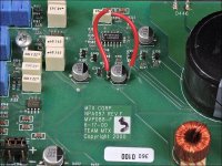
The optos aren't enabled until LED238 lights up. If that's happening too quickly to measure and you haven't powered it up without the resistor, previously, you can disable the output stage by jumping the capacitor with the cut red jumper in the photo.
Was the resistor heating up before LED238 lit up?
Was the resistor heating up before LED238 lit up?
Attachments
The optos aren't enabled until LED238 lights up. If that's happening too quickly to measure and you haven't powered it up without the resistor, previously, you can disable the output stage by jumping the capacitor with the cut red jumper in the photo.
Was the resistor heating up before LED238 lit up?
LED 238 has yet to illuminate. So yes.
- Home
- General Interest
- Car Audio
- MTX 1501d (old design amp)