The phase plug could add high frequency extension by stoping self interference across the cone. This results in more high frequency efficiency. There could be some issues with changing the acoustic center of the midbass to be further apart depending on design. Try it?
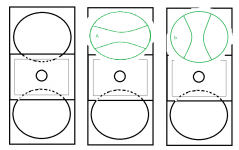
"Phase-plug" orientation: a or b ?
Links for inspiration:
OHM
ViRAY – Coda Audio
Most of these are linearray-boxes and as such rotated 90deg compared to my box
Another discussion:
DIY - reducing speaker beaming - Page 4 - Car Audio | DiyMobileAudio.com | Car Stereo Forum
Phase Plug Question -
Techtalk Speaker Building, Audio, Video Discussion Forum
Kind regards
Attachments
Last edited:
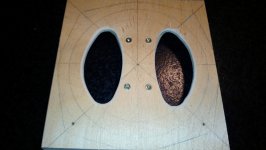
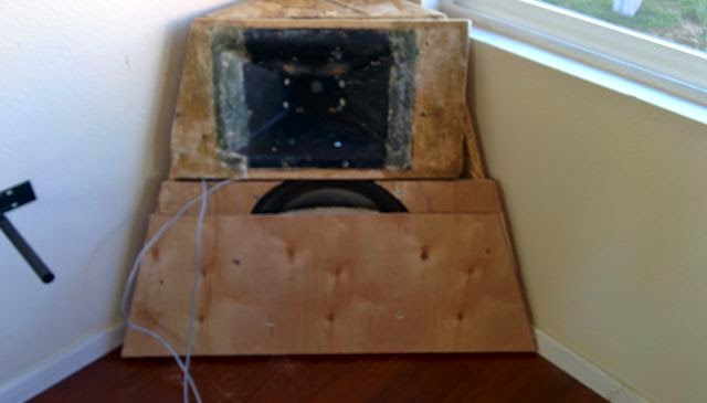
Tried making a phase-plug-device modelled after the pictures i could find. Its not perfect, but its a pretty good match to the cone.
I can only measure indoors today with tons of reflections, but so far it appears to boost approx 2,5dB from 700hz to 1500Hz. Not sure if its worth the trouble, and I still havnt measured if it does anything to beaming
Kind regards TroelsM
I can only measure indoors today with tons of reflections, but so far it appears to boost approx 2,5dB from 700hz to 1500Hz. Not sure if its worth the trouble, and I still havnt measured if it does anything to beaming
Kind regards TroelsM
Attachments

You may also want to consider making plug more like this:
with the top of the top driver blocked off and the bottom of the bottom driver blocked off. This will cause a low pass filter* on the woofers output but should also move the woofers acoustic centres closer to the wave guide helping avoid vertical beam width irregularity at the crossover frequency.
*as path length distances are increased compared to the driver without the plug
Hi Kipman.
Yes, I thought about something along the lines of what you show. Is it your design? - do you know if the cavity between the "front-cover" and cone is "filled" to remove some volume? - what about unequal loading of the cone? would that be a concern?
I haven't measured my drivers in a flat baffle because I'l never use them in a flat baffle ;-) I know it would be the best way to get the raw response from the driver, but my reasoning is that I might as well include the intended cabinet in the measurements from the start. Does that make sense?
Kind regards TroelsM
Hi Kipman.
Yes, I thought about something along the lines of what you show. Is it your design? - do you know if the cavity between the "front-cover" and cone is "filled" to remove some volume? - what about unequal loading of the cone? would that be a concern?
I haven't measured my drivers in a flat baffle because I'l never use them in a flat baffle ;-) I know it would be the best way to get the raw response from the driver, but my reasoning is that I might as well include the intended cabinet in the measurements from the start. Does that make sense?
Kind regards TroelsM
Its not my design I think its Patrick Batemans from one the threads you linked. If you added a volume filler it depends whether the lowest low pass filter frequency is caused by the path length difference to the exit from different points of the cone or by the volume of air trapped under the plate. If the low pass characteristic is caused by path length difference primarily filling in the volume wouldn't have a great effect. What attracted me to the design is that the point in space the midbass is radiating from is located closer to the horn and so the polar response around the crossover in the vertical plane should be improved.
the flat baffle would be a good comparison point, there would be little point in adding a volume filler if the response is already as extended as the flat baffle case.
- Home
- Live Sound
- PA Systems
- MTM configs for small PA top