Hi Folks,
I knocked together a quick proof of concept manifold design subwoofer yesterday and would like some help understanding the measured impedance curve.
Woofer is a JBL 2217 and the cross section of the box looks like this
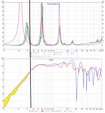
 Here is the impedance measurement vs the Hornresp simulation

I am yet to measure the frequency response, but the lack of height in the measured impedance peaks has me scratching my head and has me wondering if I missed something in construction. The peaks and troughs are encouragingly closely aligned, however.
Is this the sign of a leaking box? A badly braced box? The driver does have a very, very slight rub between the voicecoil and magnet (one that is not obvious unless playing a 10hz wave at high volume of moving the speaker by hand at the right angle) could it be a result of this?
I understand that impedance curves can be very valuable in analysing a DIY speaker, but I will confess to having very little knowledge regarding how to read one.
Any pointers would be appreciated. I haven't been able to find much in the way of explaining this topic when googling.
I knocked together a quick proof of concept manifold design subwoofer yesterday and would like some help understanding the measured impedance curve.
Woofer is a JBL 2217 and the cross section of the box looks like this
I am yet to measure the frequency response, but the lack of height in the measured impedance peaks has me scratching my head and has me wondering if I missed something in construction. The peaks and troughs are encouragingly closely aligned, however.
Is this the sign of a leaking box? A badly braced box? The driver does have a very, very slight rub between the voicecoil and magnet (one that is not obvious unless playing a 10hz wave at high volume of moving the speaker by hand at the right angle) could it be a result of this?
I understand that impedance curves can be very valuable in analysing a DIY speaker, but I will confess to having very little knowledge regarding how to read one.
Any pointers would be appreciated. I haven't been able to find much in the way of explaining this topic when googling.

Congratulation, you were vary fast building this new Box.
I'm not the must experienced and knowledge guy, but your impedance measurement looks very good. Did you measured also the frequency response?
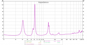
Attached you can see the TH-SS I build in the past, the first impedance peak is not aligned and real measurements in general will present lower peaks.
I think when you have leaks or effects of indoor walls, the impedance measurements will not be as smooth as the one you are presenting. Take a look at the attachment #2.
I'm not the must experienced and knowledge guy, but your impedance measurement looks very good. Did you measured also the frequency response?
Attached you can see the TH-SS I build in the past, the first impedance peak is not aligned and real measurements in general will present lower peaks.
I think when you have leaks or effects of indoor walls, the impedance measurements will not be as smooth as the one you are presenting. Take a look at the attachment #2.
Attachments
reduction in peak height means more damping of the resonances so more energy loss than expected, I have also noticed this with my own boxes compared to hornresp simulations but not to the extent of this.
sorry likely dumbass question but i'm trying to understand the implication of the presented data....if the measured impedance is lower, does that not translate to more acoustic output...???
so congrats on bettering the hornresp sim...no?
so congrats on bettering the hornresp sim...no?
So does this mean vibrating panels and ports not functioning as well as they should?reduction in peak height means more damping of the resonances so more energy loss than expected, I have also noticed this with my own boxes compared to hornresp simulations but not to the extent of this.
I did a quick frequency response measurement near my garage and the results weren't flattering. I need to get it away from some buildings and I'll do a 28.3v/10m measurement. My gut feeling is that the low end is not as powerful as the simulation. I did spend some time playing bass guitar through the box with it low passed at 200hz, and it certainly provides more low end than I will ever need for bass guitar.Congratulation, you were vary fast building this new Box.
I'm not the must experienced and knowledge guy, but your impedance measurement looks very good. Did you measured also the frequency response?
A friend and I have also built a much larger box with similar layout with the intent of being a sub for DJing that will work down to 40hz. It's loaded with a 2226. Results for that, and the cabinet I have built will be posted once we've done the measurements.
Last edited:
HR only accounts for any box damping for basic sealed, vented AFAIK, i.e. QL = 7, so your measurement is showing how much the alignment acoustically damps the driver. All things considered, kudos to the designer if the driver's Fs was in the 50s, but the 'squashed' lower peak implies one in the 40s.
If there's leaks, the lower two peaks would in theory be 'collapsing' towards the driver's single open air impedance.
If there's leaks, the lower two peaks would in theory be 'collapsing' towards the driver's single open air impedance.
Fs of the driver is 45hz.HR only accounts for any box damping for basic sealed, vented AFAIK, i.e. QL = 7, so your measurement is showing how much the alignment acoustically damps the driver. All things considered, kudos to the designer if the driver's Fs was in the 50s, but the 'squashed' lower peak implies one in the 40s.
If there's leaks, the lower two peaks would in theory be 'collapsing' towards the driver's single open air impedance.
I'm not sure I understand what you mean by "collapsing" towards the driver's single open air impedance. Do you mean that the two peaks would have lower amplitude (as they do), or that the peaks would be shifted closer to each other, or something else entirely?
Assuming the leak's big enough, the back peak fades? away, combining with?/leaving just the driver's impedance peak + the front chamber's peak, i.e. worst case is it acts as an open back box, comb filtering with its acoustic low pass filter (front horn).
Hi,
Check for leaks. I get lower peaks of impedance on my physical models when they're not rigid and sealed well to have no air leaks. Anecdotal maybe, but it's the only way I've replicated what you're seeing.
Very best,
Check for leaks. I get lower peaks of impedance on my physical models when they're not rigid and sealed well to have no air leaks. Anecdotal maybe, but it's the only way I've replicated what you're seeing.
Very best,
Box losses. The measured impedance peaks will never be as high as predicted by Hornresp as the Hornresp model doesn't take losses into consideration.
Leaks and improper bracing will result in increased box losses.
Leaks and improper bracing will result in increased box losses.
Right, re HR, some other programs, but have only seen this much damping from box acoustic loading, so assume from ya'll's experience that all my boxes I measured (admittedly not that many) were rigid/massive/sealed enough, so good to finally get confirmation my box building advice over the decades has been/is 'sound'. 😉
Example,
Here's my WinISD model.
Followed by my final build with its actual measurement.
Below both of them is the overlay of the two. They're actually very close. But the peaks are not as high, but not crazy low.

Now to contrast this, here's my pre-final physical model I built out of crappy OSB plywood and didn't take care to seal it (just held together with screws and clamps). It was leaking so bad I couldn't even get the impedance of the port to show up!

And here's the crappy physical model when I handled some of the leaks. It's still bad but its better than the above and I could at least verify I was in the ball park for my port.

Very best,
Here's my WinISD model.
Followed by my final build with its actual measurement.
Below both of them is the overlay of the two. They're actually very close. But the peaks are not as high, but not crazy low.
Now to contrast this, here's my pre-final physical model I built out of crappy OSB plywood and didn't take care to seal it (just held together with screws and clamps). It was leaking so bad I couldn't even get the impedance of the port to show up!
And here's the crappy physical model when I handled some of the leaks. It's still bad but its better than the above and I could at least verify I was in the ball park for my port.
Very best,
Yeah, it was the dramatic drop that got me to dismiss any leaking because using HR I had to use truly packed levels of damping to get half that much lowering, but no problem getting even more than his measurement with acoustic loading.
That model is missing the impact of the driver's Le.Example,
Here's my WinISD model.
That model is missing the impact of the driver's Le.
How can I correct it? Thanks!
Very best,
I'm not a WinISD user, but I think there's an option in the model to enable Le.
I will take a look, thanks!
Very best,
Here's a frequency response measurement done using Keele's nearfield technique summing the two sources and adjusting for area. Brought back to 2.83v/1m, the 50hz sensitivity is around 100db.Congratulation, you were vary fast building this new Box.
I'm not the must experienced and knowledge guy, but your impedance measurement looks very good. Did you measured also the frequency response?
Attached you can see the TH-SS I build in the past, the first impedance peak is not aligned and real measurements in general will present lower peaks.
I think when you have leaks or effects of indoor walls, the impedance measurements will not be as smooth as the one you are presenting. Take a look at the attachment #2.
With some gentle eq (taking out 6db at 125hz and boosting 2.5db around 55hz, there's are very usable 50-170hz frequency range. It was a super simple build and the wood is cut ready for the second box. They'll end up as powered boxes using Getshow DSP plate amps which are on their way.
Lastly, after measuring the woofer with DATS, the impedance plots of simulated vs measured are significantly closer.
- Home
- Loudspeakers
- Subwoofers
- MTB Manifold - Help Interpreting Impedance Measurements