Mrfeedback wrote:
Where did you get this information? Are you saying that the read head takes an analog signal and "slices" of the top and bottom peaks to make a square wave???? Hence how the threshold for "slicing" can vary????
I thought that CD players used the same principle as every other digital storage and communicaitons device uses to detect data through analog.... zero crossing? In other words, the signal may be "analog" (but varying in width), but the bits are actually where the change occurs in the signal, so that there can be little problem from noise. The detector is clocked such that when the crossing occurs within the read window, in coincidence with the fixed clock rate, there is detected a one, whereas if there is no crossing, the result is a logical zero (using an AND gate, I guess). Is this not how CDs work? Jitter is a problem only insofar as the more the jitter, the liklihood is there for misreading a bit, due to varying drive speeds. Well, as far as hard drives and other data stream devices are concerned, that I know of.
Please tell me because I really am not sure. It has been a long time since I read how CD data is read, technically, and I am having a hard time finding any real technical documentation.
Thanks!
Gabe
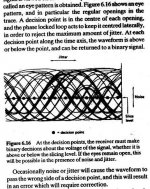
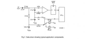
The data wavefom coming off the disc is an analog waveform. This is converted to a squarewave (rectangular) data stream by a 'data slicing' circuit stage. If the power supply to this stage is modulated (noisy), the threshold level varies and timing jitter is introduced into the data stream, and this jitter is very audible.
Where did you get this information? Are you saying that the read head takes an analog signal and "slices" of the top and bottom peaks to make a square wave???? Hence how the threshold for "slicing" can vary????
I thought that CD players used the same principle as every other digital storage and communicaitons device uses to detect data through analog.... zero crossing? In other words, the signal may be "analog" (but varying in width), but the bits are actually where the change occurs in the signal, so that there can be little problem from noise. The detector is clocked such that when the crossing occurs within the read window, in coincidence with the fixed clock rate, there is detected a one, whereas if there is no crossing, the result is a logical zero (using an AND gate, I guess). Is this not how CDs work? Jitter is a problem only insofar as the more the jitter, the liklihood is there for misreading a bit, due to varying drive speeds. Well, as far as hard drives and other data stream devices are concerned, that I know of.
Please tell me because I really am not sure. It has been a long time since I read how CD data is read, technically, and I am having a hard time finding any real technical documentation.
Thanks!
Gabe


Free...
Hi Gabe,
Sorry about delay in getting back to you - weekend, GF, etc.
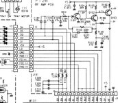
Anyway, if you study the above circuits you will see that they are all single (B+) supply operation.
If these supplies is noisy, additional noise is directly coupled into the HF waveform and this may confuse the Data Slicer decision stage, introducing actual data errors or at least timing errors (jitter).
I know that this squared waveform is passed into a FIFO buffer that theoretically should eliminate this jitter, but in practice a noisey/jittery HF waveform causes data corruption that may or may not require data error correction or interpolation.
The disc spin speed control signal is also derived from the incoming HF waveform, and a noisey HF waveform will cause an overly erratic spin servo error signal.
Wild servo currents cause other supplies to be noisey (typical lousy earthing layouts are the main cause) and can cause other feedbacks.
In my experience in some past modding, seperated transformer supplies for servo and digital/audio out sections, corrected earthing arrangements, and simply improving supplies to the initial analog preamps and initial processing chips stages is a disarmingly effective improvement.
The audio result is to add a calmness - much reduces erratic fine unmusical haze and HF glare/essing.
CD43_53_63 Service Manual.pdf is the 9.6M file I downloaded from somewhere yonks ago.
In some (most ?) earlier cdps, the initial preamps and data slice/decision stages were discrete and external to the first processor, but I don't have HD copies.
If you study the above stuff you should get the point.
Other schematics are worth a close look too.
Cheers,
Eric.
Hi Gabe,
Sorry about delay in getting back to you - weekend, GF, etc.
Anyway, if you study the above circuits you will see that they are all single (B+) supply operation.
If these supplies is noisy, additional noise is directly coupled into the HF waveform and this may confuse the Data Slicer decision stage, introducing actual data errors or at least timing errors (jitter).
I know that this squared waveform is passed into a FIFO buffer that theoretically should eliminate this jitter, but in practice a noisey/jittery HF waveform causes data corruption that may or may not require data error correction or interpolation.
The disc spin speed control signal is also derived from the incoming HF waveform, and a noisey HF waveform will cause an overly erratic spin servo error signal.
Wild servo currents cause other supplies to be noisey (typical lousy earthing layouts are the main cause) and can cause other feedbacks.
In my experience in some past modding, seperated transformer supplies for servo and digital/audio out sections, corrected earthing arrangements, and simply improving supplies to the initial analog preamps and initial processing chips stages is a disarmingly effective improvement.
The audio result is to add a calmness - much reduces erratic fine unmusical haze and HF glare/essing.
CD43_53_63 Service Manual.pdf is the 9.6M file I downloaded from somewhere yonks ago.
In some (most ?) earlier cdps, the initial preamps and data slice/decision stages were discrete and external to the first processor, but I don't have HD copies.
If you study the above stuff you should get the point.
Other schematics are worth a close look too.
Cheers,
Eric.
Re: Free...
Perhaps this was it.mrfeedback said:CD43_53_63 Service Manual.pdf is the 9.6M file I downloaded from somewhere yonks ago.
Hi Mrfeedback and all others,
thanks for your replies, but I am still a little confused, especially in light of the following I found at this web site: http://electronics.howstuffworks.co...ington.edu/conselec/CE/kuhn/cdaudio2/95x7.htm
From the above I gather that the "RF' created by the reading of "pits" of varying length is still read using the zero crossing method, power supply polarity notwithstanding (a capacitor in the right place can take care of making it so), where when the signal crosses the "zero", it is read as a one, whereas during the other "T" cycles if there is no signal crossing, the result is a logical zero. The rest of the signal, according to the article, is used for servo control, error correction, etc.
I guess I am going to have to seek several different publications, and a good schematic, one which breaks down the compoonents a bit more discreetly in order to understand this.
Again, thanks so much for all your replies. This is fascinating. Learned much from you.
Gabe
thanks for your replies, but I am still a little confused, especially in light of the following I found at this web site: http://electronics.howstuffworks.co...ington.edu/conselec/CE/kuhn/cdaudio2/95x7.htm
As the laser beam scans across these pits, a very distinct RF signal is formed. The shortest wavelength in this signal (highest frequency) is produced by the 3T pits. The longest wavelength in the signal (lowest frequency) is produced by the 11T pits. The zero crossings of the RF signal represent the edges of the pits -- and thus the binary "1s" in the data stream[2]. (Notice that the longer the wavelength, the larger the amplitude of the signal.)
From the above I gather that the "RF' created by the reading of "pits" of varying length is still read using the zero crossing method, power supply polarity notwithstanding (a capacitor in the right place can take care of making it so), where when the signal crosses the "zero", it is read as a one, whereas during the other "T" cycles if there is no signal crossing, the result is a logical zero. The rest of the signal, according to the article, is used for servo control, error correction, etc.
I guess I am going to have to seek several different publications, and a good schematic, one which breaks down the compoonents a bit more discreetly in order to understand this.
Again, thanks so much for all your replies. This is fascinating. Learned much from you.
Gabe
- Status
- Not open for further replies.
- Home
- Source & Line
- Digital Source
- mrfeedback: a question plse