Was also wondering if you thought the COD was better then the Opus? Meant to ask this before I ordered but oh well I suppose lol.
Re: USB Bus or Self Powered
Whatever happened with the Ethernet module?
FWIW I am also working on an Ethernet based module, but that me be a while in coming.
Cheers!
Russ [/B]
Whatever happened with the Ethernet module?
Ethernet module ...
Russ I don't want to hijack this thread, but music distributed via Ethernet is one of my interests. What were you thinking of doing?
Russ I don't want to hijack this thread, but music distributed via Ethernet is one of my interests. What were you thinking of doing?
It was a really old post so who knows. Also been wondering about that LCD controller module 🙂 Like a year ago you said a few weeks you would have a PCB not sure what happened after that.
some of the projects I work on have never made it to TPA production. Partly because they are just too complex to thrust upon the unsuspecting. 🙂
1) Ethernet audio, I have been working on an AVR32 solution that talks to a slim server, and can stream PCM
2) I have made several LCD controllers with IR remote and rotary encoder control. Its just very very complex, and I am working on making it simpler for every one. It will eventually come. In fact I have made a lot of progress in just the last week. Starting with a new AVR USB uC which can be programmed by the end user (for targetted firmware etc) just by directly plugging it into their PC. Its like a little key fob. Its designed to plug into a host module. I will start a thread about it when I can.
Keep in mind, this is just a hobby for me too. I don't get to work on this stuff as much as I would like.
Cheers!
Russ
Yeah I understand that Russ was just curious as they were a few things I was looking forward to 🙂
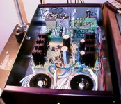
Here's my dac built with a combination of TPA Spdif receiver module, a couple of bare board COD dac boards and a bare IVY.
The cods are configured in mono mode, and the currents are summed at the outputs. I use a single IVY for I/V conversion and use that to drive a pair of UTC A-21 line mixing transformers for balanced to unbalanced output. It works really well.
I found with a pair of cod boards that the most consistent operation occurs with the receiver and dac boards stacked. I kept the I2S lines very short as I did have problems with the SCK line interference.
I built up the CODS, and IVY over the course of a few week nights. I recommend this route only for those who are very sure of their smd soldering skills - not a trivial task to solder these components in a home environment. The modules will be less hassle for most.
There are 4 separate supplies, two 7V digital supplies based on Rohm BA17807, and a set of analog supplies somewhat similar to the Jung super regulator with a pre-regulator and LME49710 based high gain fast integrator for error correction, and a TL431 reference.
My new dac is already outperforming a heavily tweaked Zhaolu 2.5A, and with further changes should get even better.
Attachments
Excellent work Kevin, great project. 🙂 You are right about the soldering, its not exactly easy. In fact I only know a couple people who have built them up from bare PCBs.
I am glad you like it. I hope you enjoy it.
Cheers!
Russ
I am glad you like it. I hope you enjoy it.
Cheers!
Russ
Bgt said:An externally hosted image should be here but it was not working when we last tested it.
mode 0-2 setup window, its on 96khz now.
Brian, the sound is awsome😀
Did you use PCB material for this?
Mazuki said:I was thinking about buying the USB receivers to interface with a SAA7220+TDA1541A. I'm just not sure about the I2S output of the USB receiver. If it outputs in 24-bit I2S, will the SAA7220 still recognise the signal? Can I set the PCM2707 to output 16/44.1khz?
I was wondering about the same thing. From the datasheet I don't see how the PCM2707 can output a 24-bit signal. It's only specified for 16 bits. Is there a typo somewhere?
If you feed the usb receiver with a 16-bit/44.1kHz signal, shouldn't that give 16-bit/44.1kHz I2S output?
BrianDonegan said:In I2S mode, the USB module (PCM2707) will output 16-bit data.
Brian
!6/44k1 or 16/48k?
allan
awpagan said:
Brian
!6/44k1 or 16/48k?
allan
Output sampling frequency is the same as the input. If you set up your software player (Winamp, Foobar or whatever) for 48kHz you will get 48kHz out from the receiver also.
Right? 🙂
I admit to being something of a newbie when it comes to the digital domain aspects of our hobby.
But it puzzles me - and I ask only for understanding, not to re-ignite a debate - why we would be concerned with the jitter performance of a clock at audible frequencies, when that clock is running cycles of digital circuits at many times that frequency band.
The clock either provides a pulse within the "correct" time window 25 million times a second - in which case it has a good jitter performance within the context of the circuit in question - or it doesn't in which case it would be poor. Seeing as the clock isn't running in the 10khz range, it's jitter performance within that range is surely irrelevant?
We are not, after all, listening to the clock (at least I prefer musical content running through my DAC).
Am I missing a key point here?
Thanks
Mark
Hello Mark,
The key thing to get ones head round is that a clock is actually an analogue waveform, and it's operation is intimately tied to the analogue output of the DAC. There are plenty of informative sites out there that will explain in more detail, complete with diagrams, which make it easier to understand.
Cheers,
Dan
Simply put, the phase noise on the clock becomes 'rolled' into' the amplitude response of the DAC. That might sound counterintuitive, but it is audible, and so its the rather low-frequency components of this 'wander' that are the worst offenders.Seeing as the clock isn't running in the 10khz range, it's jitter performance within that range is surely irrelevant?
We are not, after all, listening to the clock (at least I prefer musical content running through my DAC).
Am I missing a key point here?
For full recovery of basic 16-bit resolution at 44.1Khz, you need jitter at least '16bits' smaller than the sampling interval. That's 22uS/(2^16), or 350pS. At 4x oversampling the clock has to be 4x better, or below 100pS, and so on. Amazing, but true.
One key thing to remember about all this clock discussion, is that when using the metronome, the master clock (the clock on the metronome) is the reference clock for "everything", all outputs are slaved to that clock,bit clock, word clock, and the data. So everything is relative to that clock. This eliminates a lot of issues normally associated with Jitter. That is why we normally use the output in master mode. 🙂
The output will be entirely driven(clocked out) by the on board clock. So as long as the DAC and the ASRC share the exact same clock there should be virtually no (physical limitations not related to the XO apply come into play) effective jitter on the output since everything on the output is relative to the same master clock. As long as all the PCM outputs are in harmony, that is synced to the same clock, things should be just peachy. 🙂
One other very cool aspect of the Crystek part is that (if the datasheet is to be believed) it has no sub harmonics. These are the usual culprits that introduce jitter.
Cheers!
Russ
Jitter or not, this resampling module introduces a whole lot of noise. There's no doubt about it, the sound is better without the metronome. With the metronome the sound is somewhat tiresome and unpleasant, and the higher the sampling frequency the worse it gets. Maybe the dac doesn't like the higher clock- and sampling rate?
You must have something wrong because with so many people loving the sound of the Opus + Metronome and then you saying its horrible and introduces so much noise and what not somethings gotta be wired up wrong or something. Not trying to question your ability to assemble it but it just seems odd that there have been few to no complaints about it and the ones that were are usually a setting set wrong or something and then you come in and say its absolutely horrible.
- Home
- More Vendors...
- Twisted Pear
- Mr White's "Opus", designing a simple balanced DAC