That's a good idea though I can easily get some aly tubing from work.It's just finding someone with a bandsaw to cut it for me.Would be about 10mm wall thickness so a with a bit of filing sharp edges wouldn't be a problem.Then could take off top plate and drill fixing holes,mark through to the bottom of the tubing and drill and tap it.Sounds like a plan...
Well black is a good conductor of heat... aka like heatsinks... plus it did not look good enough plain stainless. I did try polishing it but it would have took ages.
The idea is to place the shield in front of the existing transformer cover. I have the EI core type with a cover already over them but this cover gets very hot. The shield will sit 1cm infront of this to block, absorb and raditate the heat. So the theory goes...
I know exactly what I'm doing...honest 😕
Re heat shield
Hi Swamp
I am not sure that that is the right way to go about it....I see where you are coming from with the heatsink but in this instance I thought the idea was to get rid of the heat in that area which was why I thought it needed to be silver or shiny rather than dull....
I quite like the idea of chimneys a la Unison Research but made of metal...which would funnel the heat away...
catch you later steve
Perhaps a less intrusive solution would be to mount a plate on the inside of the cage if you didn't want to change the look of the amp.Must admit I like the idea of the aly chimneys though
hi all
I have just fitted a heatshield to my Mr Liang amp and now the transformer covers dont get hot,I did think the transformers might be getting hot but now everything is cool.Hope this helps.
I have just fitted a heatshield to my Mr Liang amp and now the transformer covers dont get hot,I did think the transformers might be getting hot but now everything is cool.Hope this helps.
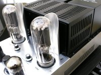
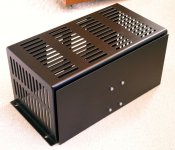
Mr Liang Heat Shield
Hi David et al
Between the two of you I think you came up with the solution....the Aluminium tubes act as reflectors and the addititional transformer shield is just that a shield for the transformers.....
Well done to you both and all.....
Steve in the UK
Hi David et al
Between the two of you I think you came up with the solution....the Aluminium tubes act as reflectors and the addititional transformer shield is just that a shield for the transformers.....
Well done to you both and all.....
Steve in the UK
I do not kow much at all about the thermo properties of color, etc, but I will point you all to a bit in Morgan Jones TA where he suggests that reflective materials near the tube would not be a great idea. I believe it is in the chapter were he is discussing the history and make up of tubes and the reason for the blackened and greyed tubes.
The reflective colors near the tube will likely reflect the heat back at the tube as opposed to absorb the heat and subsequently disperse with it. I think the shields that David made are beautiful, but painting them black would likely raise their efficacy. How much, I have no idea, I am not a materials scientist.
The reflective colors near the tube will likely reflect the heat back at the tube as opposed to absorb the heat and subsequently disperse with it. I think the shields that David made are beautiful, but painting them black would likely raise their efficacy. How much, I have no idea, I am not a materials scientist.
mr liang heatshield
Hi Joshk
I think you may be correct in your observations,I think black may be bettwer in this case .Im not sure which method is correct,although some high end designs seem to favour white.Dont know wether the heat should be absorbed or reflected regards Dave.
Hi Joshk
I think you may be correct in your observations,I think black may be bettwer in this case .Im not sure which method is correct,although some high end designs seem to favour white.Dont know wether the heat should be absorbed or reflected regards Dave.
Here's a summary of the 2 methods used so far.
http://www.triode-systems.com/modules/wfsection/article.php?articleid=31
As for the best colour I do not think it is that critical as we see heatsinks both black and raw aluminium in many products. With these reflectors using aluminium is an ideal material since aluminium rapidly absorbs heat from any hotter source nearby and radiates it to any cooler area such as the environment, hence why it is used to cool CPU's pumping out 70-100W in some of the later pentium 4 CPU's like the 600 series, aka 650 etc.
The Unison research 845 uses ceramic at the back of the tube to block the heat. By using aluminium instead these shields absorb quite a bit of heat outside the 845 acting like a sink. It will then radiate this heat to the cooler air at the back and above it, and not back to the hotter tube. They maybe slightly more efficient at doing this if painted black but I don't think it is critical make or break.
The mains transformers certainly stay cool now and I think David's solution works ok and certainly better than nothing. If anyone makes anything better then please post here with pics so we can try other ideas.
Thanks for everyones ideas and suggestions.
Regards
Swamp
Mods to Mr Liang 845
Couple of things I have just remembered.
On my MkI pin 1 of V201 is not connected to earth on ther PCB, simple to do with a bit of tinned copper wire.
Normally this wiill not matter but if you are using the 6SJ7M metal can version pin 1 must be earthed for both screening and safety's sake. It was surprising how much the hum was reduced doing this.
Also the PCBs on these amps are of the Plated Through Hole (PTH) variety so you can usually remove components by heating their leads until the solder is molten, pull the lead out and then solder suck the rest of the hole clear. Fit the new component heat the lead and if possible the PCB apply solder and it will "wick " its way into the hole making an excellent joint.
There is a lot of of comment about how hot the transformers are getting and whilst I am not going to denigrate the excellent efforts here to cool things down, bear in mind that modern insulations mean that transformers can and will run very hot.
A couple of Pathos Amps I have just repaired were running very hot, not surprising as they are Class A and standing current means a dissipation of 250Watts each! When I queried this with the factory I was told that the Tx core area had been measured at 150ºC and this was well within the Tx manufacturers limits
John Caswell
mr Liang
I have a mk 3 ? version of this amp and I also noticed that only pin 1 on the input valve is grounded on one channel,will now link both together as per Johns comments.Also Iwould advise anybody who as not fitted an earth from the mains input socket to the chassis to do so for safety.
I have a mk 3 ? version of this amp and I also noticed that only pin 1 on the input valve is grounded on one channel,will now link both together as per Johns comments.Also Iwould advise anybody who as not fitted an earth from the mains input socket to the chassis to do so for safety.
Re: Mods to Mr Liang 845
Same here but I am using the china 6j4p tubes at the moment so not an issue unless I change those tubes.
John.. did you change any of the component values to run the metal 6sj7 at its correct operating point. I think it was Norbert who mentioned it but he changed a 390R cathode resistor to 1.5K. My version of the amp is a little different, it seems to be closer to the mk3 but using 5881 instead of 300B.
John Caswell said:Couple of things I have just remembered.
On my MkI pin 1 of V201 is not connected to earth on ther PCB, simple to do with a bit of tinned copper wire.
Normally this wiill not matter but if you are using the 6SJ7M metal can version pin 1 must be earthed for both screening and safety's sake. It was surprising how much the hum was reduced doing this.
John Caswell
Same here but I am using the china 6j4p tubes at the moment so not an issue unless I change those tubes.
John.. did you change any of the component values to run the metal 6sj7 at its correct operating point. I think it was Norbert who mentioned it but he changed a 390R cathode resistor to 1.5K. My version of the amp is a little different, it seems to be closer to the mk3 but using 5881 instead of 300B.
Hi John/All
Sorry for the confusion but the heat that has been talked about in the last few posts isnt about the natural Tx heat generated in use.I think this confusion is arising due to the various iterations of this amp that are extant.What we are talking about is the latest version which has caged EI Tx's in place of the original potted torroidals,which were situated in open space further away from the 845's.The newer version has the cage very close to the rear of the power valves,and as such the 845's are radiating their heat directly into the cage.Admittedly it's the cage that is getting hot and not the Tx's,but that is leading to a concern that the mains tx's are receiving too much heat and may in time start giving it the mission impossible and give you 5 seconds to smoke your pipe! 🙂
So that's the **** as it stands.My worry is that all the secondary wiring that comes off the front of the tX's will get a suntan from the heat,but the thing I'm really worried about is given the drunken nature of my last couple of posts,nobody here will ever take me seriously ever again.🙂
If the cage is getting hot and not the transformers, isn't the cage shielding the transformer? Maybe I am not quite getting what you are trying to achieve, but it looks to me like you are building a shield to protect a shield, rather than protecting the transformers. Are you in fact worrying over nothing?
Cheers,
Chris
Cheers,
Chris
That's true to some extent but my personal concern is that the wiring exits the transformers at the front so is exposed to all the heat from the 845's.Heat is not good for wiring insulation long-term so that's why i'm thinking of making a shield.
Hi Folks,
Have had the amp on tonight and I've noticed a low-level ringing sound coming from it.Bit hard to pin down where exactly it's coming from. Not sure if it's from the valves or inside the chassis.It's not signal dependant so must be mechanical in nature.Anyone noticed similar?
Regards,Ali
Have had the amp on tonight and I've noticed a low-level ringing sound coming from it.Bit hard to pin down where exactly it's coming from. Not sure if it's from the valves or inside the chassis.It's not signal dependant so must be mechanical in nature.Anyone noticed similar?
Regards,Ali
Re: Cathode Resistor for 6SJ7
Well my friend Dave changed the resistor to around 1.5K in his Mr Liang and the voltages increased as expected to 150V on the anode and 100V at g2. It did sound better than when run without the resistor change but the gain seems very low compared to the China 6J4P and it does not sound quite right. the volume had to be past 1/2 way compared to 1/4 way as standard with china 6J4p. It seems to have no life with the 6SJ7, yes less muddy sounding but it is like there is not enough gain to drive the next stage 6l6/5881. The china 6J4P is better in many ways but it is muddy sounding.
What about the 6SK7 ? Has anyone found any Russian 6J4P's anywere. It seems this first tube is letting Mr Liang down but I am not sure if the 6SJ7 is the best replacement without futher mods.
Regards
Swamp
Norbert said:Don't forget to change the value of the 6SJ7's cathode resistor. Without the change anode voltage was about +100V and g2 voltage +50V which is not what a 6SJ7 likes to see. In my amp the stock cathode resistor was only 390 Ohm.
I changed it to 1.5 kOhm and as a result anode voltage came up to 150V and g2 voltage to 100V. Cathode voltage is now 3.4V and anode current is 1.6mA.
The 845 needs about 290Vpp to deliver full power which makes the anode voltage of the first stage >= 150V a must!
Best regards,
Norbert
Well my friend Dave changed the resistor to around 1.5K in his Mr Liang and the voltages increased as expected to 150V on the anode and 100V at g2. It did sound better than when run without the resistor change but the gain seems very low compared to the China 6J4P and it does not sound quite right. the volume had to be past 1/2 way compared to 1/4 way as standard with china 6J4p. It seems to have no life with the 6SJ7, yes less muddy sounding but it is like there is not enough gain to drive the next stage 6l6/5881. The china 6J4P is better in many ways but it is muddy sounding.
What about the 6SK7 ? Has anyone found any Russian 6J4P's anywere. It seems this first tube is letting Mr Liang down but I am not sure if the 6SJ7 is the best replacement without futher mods.
Regards
Swamp
- Status
- Not open for further replies.
- Home
- Amplifiers
- Tubes / Valves
- Mr. Liang audio amplifiers