I have been working (on & mostly off) for the past 4 years on a Joe Curcio (www.curcioaudio.com) MQ-100 ampifier (2x6922 drivers, 4x6550 output). As I am writing this, both monoblocks are powered up for the final bias stability test, and I will listen to them for the first time either late tonight or tomorrow!
I will post pictures as soon as they are operational.
I will post pictures as soon as they are operational.
CURCIO AMP
Salut Gilid,
I,for one couldn't have waited.
Give us the news asap,pls.
BTW,are you familiar with L'Audiophile?Jean Hiraga?
If so,don't you think these works (books) are worth translating to English (Franglais in my case) ?
Rgds,
Salut Gilid,
I,for one couldn't have waited.
Give us the news asap,pls.
BTW,are you familiar with L'Audiophile?Jean Hiraga?
If so,don't you think these works (books) are worth translating to English (Franglais in my case) ?
Rgds,
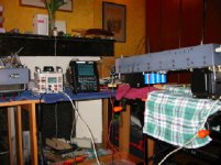
I am now in that frustrating troublehooting phase of a project - so close to being fully completed, but so far away...
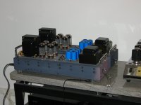
Here is a photo of the 2 amps before their first real world test. Back to the bench for more checkouts!
Fdegrove: Hiraga book 'Initiation aux amplis a tubes' sits on my bookshelf - a superb reference, especially of the single ended movement. A real inspiration. I do not know his magazine too well, though.
I will keep the group posted on my progress with my amps.
Attachments
AMP
Dave,
Didn't you spot the "Sonic Frontiers" logo on it.
At least that's what it reminds me of.
BTW,these new amps just ooze WAF don't they?
Cheers,
Dave,
Didn't you spot the "Sonic Frontiers" logo on it.
At least that's what it reminds me of.
BTW,these new amps just ooze WAF don't they?
Cheers,
Re: AMP
Now that you mention it, yes that is the SF logo.
dave
fdegrove said:Didn't you spot the "Sonic Frontiers" logo on it.
Now that you mention it, yes that is the SF logo.
dave
AMP
Gilid,
Your amps look superb.Sexy!
Congratulations!
RE:Jean Hiraga:The older issues of "L'Audiophile" are still the best.
There is someone in France who has put them all on CD.
The url is http://perso.club-internet.fr/ndaviden/revues.html
Happy listening.
Gilid,
Your amps look superb.Sexy!
Congratulations!
RE:Jean Hiraga:The older issues of "L'Audiophile" are still the best.
There is someone in France who has put them all on CD.
The url is http://perso.club-internet.fr/ndaviden/revues.html
Happy listening.
Good eye - the amp on the right is a Sonic Frontiers SFS-50. A few years ago, I stripped it, had it nickel plated, and upgraded the capacitors. It is a fine sounding amp, with decent WAF (Fdegrove!).
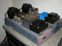
I actually did consider aesthetics when I started to work on them. I had in mind a 1950's functional look, much like you would find on purpose built lab instruments at that time. Personally, I quite like the 'form follows function' look. Actually, my wife likes them.
A cage will fit around the capacitor banks, for safety.
AMP
Gilid,
Seems to me you put in at least as much work in the looks as in the actual electrical parts.I bet it looks neat on the inside as well.
Personally, I quite like the 'form follows function' look. Actually, my wife likes them.
Said the Porsche collector??
😉 😉
Again congratulations!Inspiring looks!
Rgds,
Beautiful
Congratulations!
Looks very nice indeed
Good mechanical engineering.
Hope it sounds as good as it looks.
Congratulations!
Looks very nice indeed
Good mechanical engineering.
Hope it sounds as good as it looks.
Amps finally performing!
After a long road, my amplifiers are finally performing! After an evening of focussed listening, I am more and more impressed. Very dynamic, with sky high headroom - I did not manage to reach the limits.
I am posting a few pictures of the costruction process:
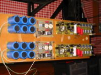
The circuit modules:
1) Capacitor bank
2) driver board
3) power supply rectification & regulation for screen & bias supplies
After a long road, my amplifiers are finally performing! After an evening of focussed listening, I am more and more impressed. Very dynamic, with sky high headroom - I did not manage to reach the limits.
I am posting a few pictures of the costruction process:
The circuit modules:
1) Capacitor bank
2) driver board
3) power supply rectification & regulation for screen & bias supplies
Attachments
continuation
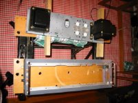
Here is the chassis. The sides are built of aluminium 'c' section, 90 mm high, 3 mm thick. I cut them at 45 deg, and had them welded together. Welds were then ground smooth. Top plate is 8 mm thick aluminium plate.
After all cutting/drilling/machining operations were over, I used an orbital sander to smooth out imperfections. I then had all components sandblasted, and then anodized in gray.
Attachments

cont
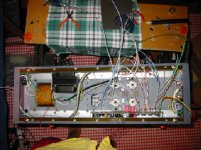
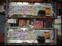
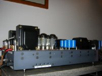
All modules fully installed & tested. Notice that the regulator cards are installed on opposite sides. That is to allow access to the bias pots on each amplifier when they are placed beside each other. The 4 bias pots can be seen on the circuit boards.
All power line wiring is shielded, with the shield grounded. Note the star grounding point close to the power transformer.
Attachments
last!
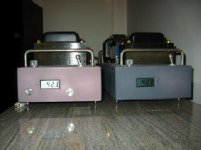
Side view, showing access to the bias pots.
Summarizing, this was a good project. Certainly, I would perhaps do things a bit differently, but overall, this has been a rewarding project. If any other board members built this amp, I would be interested in their opinions.
Many thanks to Joe Curcio for an inspired design, and to Mike Lefevre of Magnaquest for the superb transformers.
Now, on to improvements!
Attachments
- Status
- Not open for further replies.
- Home
- Amplifiers
- Tubes / Valves
- MQ-100 Project close to completion!