tiroth said:The order is in! There were a total of 87 orders. I'll be donating at least $1 a board to DIYaudio once I get I verify the orders are correct.
I should receive the boards on or before May 20th. The annual is coming.
I've ordered additional boards, so I'll continue to accept orders as long as I have boards available. Thanks everyone.
You mean Manual correct?
Anthony
Quite so--an amusing typo. Perhaps more sleep is advisable?
I was actually expecting more than 87 boards, but my minimum was 50 and that was no problem. Definitely a success. 🙂 I'd really like to get some of Jens' improved MOX boards ordered because MOX and MOXlite should work in tandem--design on one, build on the other, and reuse MOX for the next project. Hopefully in 6 months or so I'll put another buy together that elicits more interest.
I was actually expecting more than 87 boards, but my minimum was 50 and that was no problem. Definitely a success. 🙂 I'd really like to get some of Jens' improved MOX boards ordered because MOX and MOXlite should work in tandem--design on one, build on the other, and reuse MOX for the next project. Hopefully in 6 months or so I'll put another buy together that elicits more interest.
Tiroth,
you must need that sleep.
Annual means publish each year and now you are talking about putting yourself through all this again in 6 months.
you must need that sleep.
Annual means publish each year and now you are talking about putting yourself through all this again in 6 months.
I am interested in an I-MOX buy, whenever you are ready, Tyler. Not that I don't already have too many projects in various states of incompletion. 
Hi,
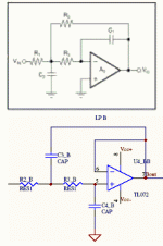
Moxlite schematic shows unity gain filter blocks. This is not the same topology as mox.
I see that unity gain can give B2 and cascading 2 sets will give L-R4.
How do you get B4?
I thought the whole idea of mox was an easily adjustable filter set to experiment with active speakers until one had them sounding just right. Then use moxlite to implement the final filter.
But how does unity gain meet this requirement?
What am I missing here?
Hi,
now going one step farther.
Can moxlite be modified either by track snip or by hard wire p2p to form MFB filter topology?
This mod is easy if gain adjustable filter blocks based on EVS&K are used.
now going one step farther.
Can moxlite be modified either by track snip or by hard wire p2p to form MFB filter topology?
This mod is easy if gain adjustable filter blocks based on EVS&K are used.
The only difference between the designs is that MOXlite doesn't need the clever circuitry for Q adjustment, since you already know the Q when you design the filter. In fact, for the Q=0.5 case, the filter components are identical between MOX and MOXlite. For other Q, they just need to be scaled appropriately.
As for compatibility with MFB--let me know if you know of a different MFB topology. As it stands, I don't see that they are remotely similar.
As for compatibility with MFB--let me know if you know of a different MFB topology. As it stands, I don't see that they are remotely similar.
Attachments
Hi Tiroth,
I had not read all the MOX threads and only just found that Moxlite is only unity gain based.
Yes, you can scale the R's and/or the C's but the maths is quite complex (for me) and is only recommended for Q <=1.1
if Q>1.1 the gain should be set for >1. This is the situation for the B4 filter when Q of one stage is 1.307 and optimum gain should be 1.31 to minimise error due to component tolerances.
Yes, the schematic for MFB is exactly as you attached to post 108.
The similarity is that both are 2 pole filters and when you draw the unity gain (moxlite) inverted with the -ve input at the top you find the component placement is almost identical with just a few track swaps and 3 extra resistors. Similarly if you compare the inverted layout of an EVS&K (mox) again component layout is even closer and this time only 1 extra resistor is required.
The advantage of EVS&K is independant setting of Q and accurate selection of frequency Rs & Cs without scaling. The advantage of MFB is independant setting of both gain and Q but at the expense of scaled Cs but you can obviate this by //ing identical Cs for the lower limb with good matching accuracy if board space is dedicated to the Hi Q filter.
All of this only applies if you want filters other than B2, B3, L-R4 and L-R6.
Maybe some of these options could be kept in mind for Moxlite V3 in a year or so's time?
I would like to compare L-R4 to B4 and unfortunately Moxlite might not let me do this thus prompting my questions. Sorry for the diatribe.
'splain dis to me!
You lost me there....and I've returned from a fruitless search.
I got the Bx's = Butterworth
I got the L-Rx's = Linkwitz-riley
whadaya mean by MFB and EVS&K?
You lost me there....and I've returned from a fruitless search.
I got the Bx's = Butterworth
I got the L-Rx's = Linkwitz-riley
whadaya mean by MFB and EVS&K?
Hi,
sorry didn't mean to lose you or anyone.
MFB is multiple feedback as posted by Tiroth. A few more components and lots more flexibility.
EVS&K is equal value Sallen & Key. Exactly the same as Mox which has gain adjust in the feedback loop. You use gain to set your chosen Q and the equal value Rs and Cs are chosen to set your F3db as usual.
Has that got you going or do you need more?
In short, I think MOXlite is everything you are asking for in terms of capabilities. The long answer:
MFB = multiple feedback
EV S&K = equal value Sallen-Key: a special case that makes the math easier
MFB generally has lower sensitivity to component variance. The only real downsides are that capacitors can get excessively small compromising HF performance. There are gain accuracy implications that really aren't relevant in this circuit. Of course, MFB also requires more components.
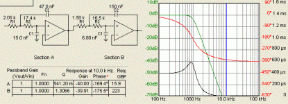
But it seems to me that all you are asking for is to be able to do intermediate Q filters, which is no problem at all! For instance, 4th order butterworth is simply Q of 0.54 and 1.3 cascaded. I've attached an example in SK topology.
There was an excellant discussion of this recently that I couldn't seem to locate. Here is a post by Svante though that outlines in general how cascaded filters operate:
http://www.diyaudio.com/forums/showthread.php?postid=488920#post488920
If you are interested in this, I would recommend that you download Texas Instrument's free FilterPro application. It makes it really easy to calculate multi-pole filters and visualize the effect on FR and phase.
MFB = multiple feedback
EV S&K = equal value Sallen-Key: a special case that makes the math easier
MFB generally has lower sensitivity to component variance. The only real downsides are that capacitors can get excessively small compromising HF performance. There are gain accuracy implications that really aren't relevant in this circuit. Of course, MFB also requires more components.
But it seems to me that all you are asking for is to be able to do intermediate Q filters, which is no problem at all! For instance, 4th order butterworth is simply Q of 0.54 and 1.3 cascaded. I've attached an example in SK topology.
There was an excellant discussion of this recently that I couldn't seem to locate. Here is a post by Svante though that outlines in general how cascaded filters operate:
http://www.diyaudio.com/forums/showthread.php?postid=488920#post488920
If you are interested in this, I would recommend that you download Texas Instrument's free FilterPro application. It makes it really easy to calculate multi-pole filters and visualize the effect on FR and phase.
Attachments
I have some familiarity with Equal Value Sallen & Key, having read about and implementing them. With the words "multiple feedback', I'm better equipped to do the search.
Thanks
Thanks
AndrewT said:Hi,
sorry didn't mean to lose you or anyone.
MFB is multiple feedback as posted by Tiroth. A few more components and lots more flexibility.
EVS&K is equal value Sallen & Key. Exactly the same as Mox which has gain adjust in the feedback loop. You use gain to set your chosen Q and the equal value Rs and Cs are chosen to set your F3db as usual.
Has that got you going or do you need more?
tiroth said:In short, I think MOXlite is everything you are asking for in terms of capabilities. The long answer:
MFB = multiple feedback
EV S&K = equal value Sallen-Key: a special case that makes the math easier
MFB generally has lower sensitivity to component variance. The only real downsides are that capacitors can get excessively small compromising HF performance. There are gain accuracy implications that really aren't relevant in this circuit. Of course, MFB also requires more components.
But it seems to me that all you are asking for is to be able to do intermediate Q filters, which is no problem at all! For instance, 4th order butterworth is simply Q of 0.54 and 1.3 cascaded. I've attached an example in SK topology.
There was an excellant discussion of this recently that I couldn't seem to locate. Here is a post by Svante though that outlines in general how cascaded filters operate:
http://www.diyaudio.com/forums/showthread.php?postid=488920#post488920
If you are interested in this, I would recommend that you download Texas Instrument's free FilterPro application. It makes it really easy to calculate multi-pole filters and visualize the effect on FR and phase.
bg40403 said:I have some familiarity with Equal Value Sallen & Key, having read about and implementing them. With the words "multiple feedback', I'm better equipped to do the search.
Thanks
My Brain hurts! 😕
heh Anthony, normally mine would as well but recently I picked up half a book(missing the cover and the first/last few pages) at a garage sale that is all about active xo's, damn well written book. I wish there was some indication of who the author or publisher is...all those pages were torn out. I've been searching the net with chunks of text from it hoping I'll get a hit. I may scan some sections and post them in PDF if I get a scanner soon.
BTW. How are those parts coming along?
BTW. How are those parts coming along?
Illusus said:heh Anthony, normally mine would as well but recently I picked up half a book(missing the cover and the first/last few pages) at a garage sale that is all about active xo's, damn well written book. I wish there was some indication of who the author or publisher is...all those pages were torn out. I've been searching the net with chunks of text from it hoping I'll get a hit. I may scan some sections and post them in PDF if I get a scanner soon.
BTW. How are those parts coming along?
Hello Bart, I think I have them all now. I will ship to you as soon as I can get to the Post Office. I have a few things to ship out, ZEN stuff for you and Aelph stuff for Mark. I could have shipped sooner, but I have been out of work for quite some time now and have been a little errr.. distracted. Apologies.
I also just finished bringing in all the parts from a GB I am helping Jason Leaman with.
Regards
Anthony
No problem...I was only curious. I still have a lot of chassis work left, waiting on trafos anyway. What's Jason working on? I may have missed it.
When searching for active filter info, try looking for transfer function and parameter calculation.
I have been looking at the MFIG filter, but desided on the S&K topology for my active filter, I thought the S&K was simpler (1 less component per second order section)
There might also be a need for an extra inverter somewhere because the the MFIG filter is an inverting filter. I think a desing example is needed to evaluate what filter is the optimal one for DIY.
The transfer function will be similar for the two filters, but the sensitivity to component changes will be different for the two filters.
I hope this helps you on your quest for info.
\Jens
Hi,
regarding Jens post,
the transfer function for all three types of 2 pole filter (unity gain, EVS&K, MFB ) are all identical if the components are accurately selected.
Re tiroth post,
When small errors creep into actual components then the transfer function starts to go astray. When gain =1 the sensitivity to errors is quite small ( a big advantage of unity gain). However as shown in Tiroth's example schematic, to achieve a 1kHz B4 filter the range of capacitors is 6n8 to 150n, selecting caps to better than 1% absolute accuracy over this range is going to be difficult if not impossible for me and probably many other DIYer's. Which is why I have based all my previous calculations on initially EVS&K but more recently MFB to avoid the high gain of an all EVS&K B4 which comes to +8.21db.
All this theory is driving me mad as well.
All I wanted was confirmation if the PCB could be altered to allow EVS&K or MFB topologies.
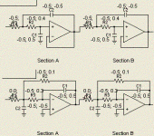
Andrew, there is no need for EV S&K! Check out the sensitivity comparison for two B4 filters. The top is SK, the bottom MFB. Yes, the MFB is less sensitive, but the difference is hardly overwhelming.
(The gain is unity for both filters.)
For both filters, the gain/Q error is never more than half the component error in this case. If you really want to be careful, you can choose your components so that a small error in one component is balanced by an opposite small error in another.
(The gain is unity for both filters.)
For both filters, the gain/Q error is never more than half the component error in this case. If you really want to be careful, you can choose your components so that a small error in one component is balanced by an opposite small error in another.
Attachments
- Status
- Not open for further replies.
- Home
- Group Buys
- MOX active crossover buy