So I received my ta8251's in the mail the other day, and I hadn't looked too closely at the physical dimensions of the pins on the data sheet, and the pins are spaced ok on each row, it's just that the second row is slightly to the side from the first row, so they don't line up and don't fit in my breadboard. I'd like to test it first, but the only way I can think of getting it to work are either making my own pcb and soldering it in, or just soldering wires to each pin and putting those wires in the breadboard. Is there a special kind of chip mount I can get for this configuration? Some standard 25 pin mount that I just haven't seen yet? Any help would be appreciated, again. Thanks.
I just checked the datasheet, and it says that the pin spacing is 1.27mm, which is exactly half of standard DIP (0.100"), and the pin planes are 2.54mm (0.100") apart.
For prototyping purposes, you MAY be able to manufacture a socket to work with this. Depending, of course, on how big the holes in your breadboard are...
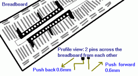
Take a standard 14 pin wire-wrap socket. Cut it in half down the middle. Cut all the pins ~7mm shorter on one half. Stuff that half into your breadboard, adjacent to the center groove, so that the "outside" (uncut) side of the socket is next to the center groove.
Next, Put two 90" degree bends in each leg of the socket half you have left over, so that the "outside" (uncut) side of that socket half is adjacent to the "outside" of the socket half which is now in the breadboard, once you insert it on the other side of the board. Now, you should be able to stick both halves in the breadboard and push them around until their heights are close, and the pin spacing from one half to the other is correct.
Then insert the IC into your makeshift socket, keeping in mind that your lead length is even worse that it normally is when breadboarding.
Hmm. Perhaps the diagram below will help explain better -- sorry for the lousy art, I was using MS Paint.
Wes
Attachments
Sorry, I just realized, my diagram shows the socket halves too far apart. They should be touching (or almost touching). But there's no way I'm drawing all those lines again. 🙂
Wes
Wes
Sounds like a good plan, probably my best option for now. I'd just like to get a sense of how the chip works before I set up a board and solder everything in. Thanks again.
I'm at work so I don't have the chip or access to the data sheet (work comps filter out non-work .pdf's), but I remember counting 25 pins total, will the 14 pin wire wrap one still work?
Yeah, but apparently my math skills are fuzzy. If it's indeed 25 pin, you can get away with a 13-pin socket (although these seem to be less common -- at least in my parts bin)
Wes
Wes
Oh, I get it, I misunderstood. I thought it was 14 total, but it's 14 to each side. I don't mind extra ones, whatever's easier for me to get is fine. Thanks for the tips.
Riight. 26 or 28 pin socket. 
Jeez, my math skills ARE fuzzy. I'll have to get my daughter (3rd grade) to help me next time I post. 😉
Hey, at least there is the right number of pins in the diagram! 🙂
Wes

Jeez, my math skills ARE fuzzy. I'll have to get my daughter (3rd grade) to help me next time I post. 😉
Hey, at least there is the right number of pins in the diagram! 🙂
Wes
- Status
- Not open for further replies.
- Home
- Amplifiers
- Chip Amps
- Mounting TA8251 on a board
