So i bought a couple of Nissei TN-73 to use on a power amp project.
These are some nice(and cheap, paid 24 bucks a piece) meters, and do have a simple way to mount them IF you use the supplied bezel. I want to go in another direction however and plan on mounting them flush to the backside of my thick wooden front panel, and bevelling the opening a bit(in essence the front panel becomes a large bezel). This unfortunately means i won't be able to use the mounting hardware that came with the meters.
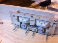
So the plan is to first glue(cyanoacrylate?) the meters side to side, then create a wooden jig and use that as a guide to glue(silicone, PU?) some screws onto the back of the meters to fasten them in this jig, then secure the jig to the back of the front panel(wood screws). The wood is Fir for the panel and plywood for the jig.
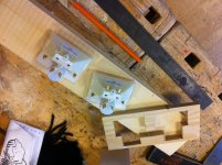
Anyone out there did something similar with their meters and/or have advice for me? Attached are the dimensions of the meter and the beginnings of the jig, laid on the front panel.
Thanks for your consideration folks!
These are some nice(and cheap, paid 24 bucks a piece) meters, and do have a simple way to mount them IF you use the supplied bezel. I want to go in another direction however and plan on mounting them flush to the backside of my thick wooden front panel, and bevelling the opening a bit(in essence the front panel becomes a large bezel). This unfortunately means i won't be able to use the mounting hardware that came with the meters.
So the plan is to first glue(cyanoacrylate?) the meters side to side, then create a wooden jig and use that as a guide to glue(silicone, PU?) some screws onto the back of the meters to fasten them in this jig, then secure the jig to the back of the front panel(wood screws). The wood is Fir for the panel and plywood for the jig.
Anyone out there did something similar with their meters and/or have advice for me? Attached are the dimensions of the meter and the beginnings of the jig, laid on the front panel.
Thanks for your consideration folks!
Attachments

Last edited:
Be very careful with "cyo" glue, it can creep and cause a bloom on plastics away from where you first apply it.
Mechanical solutions aren't my forte I'm afraid but one possible solution could be to fix the meters to a PCB that is secured vertically behind the panel. Get the dimensions and fixing holes right (oval hole for movement ?) and the meters would be a tight fit with no "direct" fixing needed. The PCB has slight flex and could be used as a natural "spring" to further keep things tight and in place.
Mechanical solutions aren't my forte I'm afraid but one possible solution could be to fix the meters to a PCB that is secured vertically behind the panel. Get the dimensions and fixing holes right (oval hole for movement ?) and the meters would be a tight fit with no "direct" fixing needed. The PCB has slight flex and could be used as a natural "spring" to further keep things tight and in place.
Thanks for the tip, looks like solvent-based glues for the meter-to-meter joint is out, for the reasons you mentioned and also because it can crack much later due to solvent stress. I'm thinking either a water based glue of some sort, silicone or even hot glue. I don't think the meter to meter joint has to be very strong, but i do believe the assembly is going to experience some vibration. 😉
The PCB idea is pretty good, but i still worry that i'll be able to get the meters exactly where they need to go, especially handcrafting the PCB. I think i'll stick with the plywood jig i have for the first trial, and once i have the meters securely attached to the jig, i should be able to precisely align the jig and meter assembly to the back of the front panel for a perfect appearance from the front.
Stay tuned for updates!
Suggestion
use the bezel and make the panel opening the size of the inner edges of the bezel so that the wood hides the frame of the bezel and rebate the bezel into the rear of the panel .
use the bezel and make the panel opening the size of the inner edges of the bezel so that the wood hides the frame of the bezel and rebate the bezel into the rear of the panel .
Hi epicyclic and thanks, thats a pretty wicked idea except it won't let me put the meters side-to-side without there being a black bar between them(from the 2 bezels). But you did give me a useful idea on mating the meters to the back of the panel, i hadn't given this much thought before, but slightly rebating them into the panel should look way better than just having them flush. Sounds very tricky to do with just hand tools however. But it should also make it way easier to get them situated perfectly, i know the eye is very sensitive to slight misalignment or asymmetry. I might even carefully sand the mating sides of the meters halfway down, so that when they mate it will look nicer.
I think ill try to figure it out as i go, will take some more photos as the build progresses. Feel free to keep the tips coming!
I think ill try to figure it out as i go, will take some more photos as the build progresses. Feel free to keep the tips coming!
Or locate the meters into a plywood sandwich made of thin panels of ply .
The front ply forms the combined meter window and holds the fronts in without a central bar , the middle ply holds the meters together as a rebate would and the rear ply holds the backs in .
The front ply forms the combined meter window and holds the fronts in without a central bar , the middle ply holds the meters together as a rebate would and the rear ply holds the backs in .
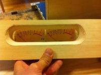
Yeah but i want to minimize the distance between the meters and the back of the panel. Here are some snapshots from my build session today.
I was stressed out as the shop was closing, so i made a mistake. I only subtracted one radius instead of two when i put down my pilot marks for the drills, so the hole is 15mm too wide. :/
But i decided(right then and there in fact) to put a small piece of wood or metal on each side of the meters and place the protection LEDs there instead of on the front of the panel. Too much work redoing the panel and wasteful of wood too.
I think this is going to work!
Attachments

Last edited:
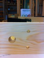
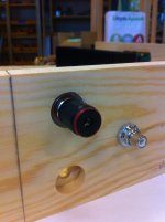
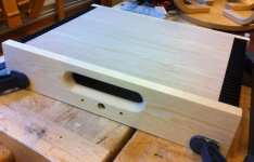
Went ahead and redid the front panel, this time form slightly thinner stock, the gap was bugging me too much. Will post some photos of the finished mounting arrangement once it's nice and dry. In the meantime, i tackled the rear panel, and i have to say i'm fairly happy with the results. The speaker posts are sunk from the outside, vice versa for the RCA jacks.
Attachments
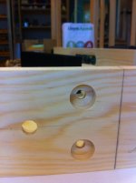
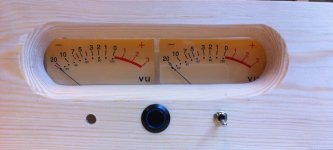
A quick update with some progress shots. I liked the older panel better with regards to snugness, but this new one will have to do. The whole build turned out to be fairly tricky to get right, i ended up having to take a hacksaw to the meters themselves(to fit the power switch), some hours of chiselwork to muscle the plywood into shape(should've used thinner plywood but this was all i had that was sturdy enough), but a lot of fun and a learning experience. The cabinet is probably around 80% done at this point.
Attachments
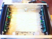
And the monologue continues... 😀 Here are a couple of shots from todays session in the shop. The lid is going to be hinged, to show off the insides but also in case i need to keep it slightly open to keep temps inside the case down.
Nice and roomy inside, plenty of space for PSU and wiring.
Nice and roomy inside, plenty of space for PSU and wiring.
Attachments
Hi Kris,
Just found this after your post in the other thread. some photo's of where you're at now would be great 🙂 and I'm jealous of your vu meters - they look nice 😎
Just found this after your post in the other thread. some photo's of where you're at now would be great 🙂 and I'm jealous of your vu meters - they look nice 😎
Yeah, i'm pretty much where the last pic shows me, except i sandpapered it. Going to try to get a mockup pic of the meters and switches in and lit soon!
Hi aspiringv, sorry for the late reply.
Actually, haven't quite thought that far ahead yet. 😉 Original plan was to try to simply drive them from the Fetzilla outputs with a suitable dropper resistor(as power meters), with a switch to take them out of the signal path if need be.
But i may end up getting one of the myriad VU meter driver boards from fleabay if it doesn't give acceptable visuals. The meters are purely eye candy, and i'm not 100% happy with how the hole for them came out. If i end up redoing the chassis i will make a hole that is more rectangular, lesson learned re trying to fit a square peg in an round hole.
BR
Kris
- Status
- Not open for further replies.
- Home
- Design & Build
- Construction Tips
- Mounting a pair of VU meters from behind the panel