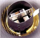
This picture from a 25 cm Backes & Müller sub was discussed in a German forum. An inductive sensor will monitor the velocity of the voice coil.
Apparently, there are four rectangular (ferrite?) magnets, setting up two gaps of the same or opposing B direction.
There is one trace in the center of the PCB that sits at the upper end of the gaps. The voltage induced in this trace would essentially be a half wave with a strong peak every time it crosses the rest position. This might actually be a position detector used for a servo that maintains the rest position of the coil constant.
The velocity sensor is probably a coil that runs around the circumference of the PCB, so the trace at the upper end might make up 1/4 of that sensor. As the VC and hence the PCB moves, the area that is inside the gaps changes and if the field in those gaps is homogeneous, a voltage proportional to the velocity will be induced. If it really works this way, the two gaps would have to have the same orientation.
The questions we could not get a satisfactory explanation for are:
- why the use of two gaps rather than one large one?
- what is the function of those fingers on the center trace that we presume is a position detector? The are parallel to the motion of the VC, so no voltage gets induced.
Attachments
Intriguing. There is a different finger pattern on the left with something that looks like a type number shown. I wonder whether those fingers have maybe a mechanical or dissipation purpose. Another possibility would be a capacitive sensor. Would it be possible that the inductive part senses the mechanical mid point position and that the fingers are part of a capacitive pick-up to sense the velocity and/or position?
Do we have an electrical diagram of the correction circuit?
Jan Didden
Do we have an electrical diagram of the correction circuit?
Jan Didden
well, this is the page the pic came from:
http://users.skynet.be/accupulse/sub_woofer.html
I am going to write him an email to ask if he has more pics.
For a capacitive pick-up, we'd need
a) a (high) voltage source
b) a motion in the normal direction of the PCB
-> not likely, I think
Back to induction:
Those textbook pics of loop area A and dphi have made me blind. There is absolutely no need that the trace run around the circumference of the PCB, the loop can be closed anywhere as long as it is not inside the gap.
So a single trace centered in the gap is enough as a velocity sensor.
Any trace that does not sit in the center when the driver is in rest position is more like an overexcursion sensor. This might be the function of the trace at the top of the pcb.
Still does not explain the function of the trace that sits exactly at the top of the gap and has the fingers.
Well, if the fingers have a mechanical purpose, they would keep the center trace from moving relative to the PCB, but this seems overkill...
Also, one would want to do this only for the velocity pickup trace where excellent linearity is needed, not on something like a position or overexcursion sensor.
Coming to think of it, maybe the picture was taken with the cone pushed up, so the fingered trace really IS the velocity pick-up?
Also, one would want to do this only for the velocity pickup trace where excellent linearity is needed, not on something like a position or overexcursion sensor.
Coming to think of it, maybe the picture was taken with the cone pushed up, so the fingered trace really IS the velocity pick-up?
capslock said:....This picture from a 25 cm Backes & Müller sub was discussed in a German forum.....
Any link?
Thanks.
Second page of this thread:
http://www.audioavid.com/wbb2/thread.php?threadid=2085&sid=
Warning: signal to noise on that forum is - 10 dB!
http://www.audioavid.com/wbb2/thread.php?threadid=2085&sid=
Warning: signal to noise on that forum is - 10 dB!
.....Second page of this thread...
Thanks.
My opinion is that the sensor's linearity is the biggest issue here. The Xmax is long and I don't see how it is possible to get homogenous magnetic flux with those four little ferrits. Fingers should be used IMHO for the linearization of received voltage. The upper trace looks broken if I am not mistaken. Also, the PCB looks like it has been hand-dremmelled (fine adjustments?).
Position sensors are usually independent of velocity and acceleration, which isn't the case here. Also inductive and capacitive sensors are out of the question because hard ferromagnetic materials are used.
Warning: signal to noise on that forum is - 10 dB!
")
Regards,
Milan
moamps said:
Also inductive and capacitive sensors are out of the question because hard ferromagnetic materials are used.
Milan, this is an inductive sensor for velocity. There are four ferrite magnets altogether, and there is a static magnetic field between each of the two magnets you see and its respective counterpart that you cannot see in the pic. The fingered trace is essentially vertical and sits in the vertical center of the magnetic gap in rest position. As it moves up and down, a voltage proportional to velocity is generated.
The magnetic gap should be linear inside the height of the magnets, but not outside.
I still have no explanation for the vertical fingers on the sensor trace. They certainly have no inductive function
capslock said:..this is an inductive sensor for velocity.
We have a small terminology misunderstanding here. When I said " .. inductive .. sensors are out of the question..", I was thinking of dL/dx sensors.
There are four ferrite magnets altogether, and there is a static magnetic field between each of the two magnets you see and its respective counterpart that you cannot see in the pic....
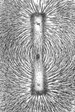
Of course. But, can you draw flux density between the magnets?
You will find a huge flux nonlinearity in the gap. (picture)
The fingered trace is essentially vertical and sits in the vertical center of the magnetic gap in rest position.
In the rest position the flux between two magnets is theoreticaly zero,IMO.
...The magnetic gap should be linear inside ....
I might be wrong but I doubt it.
I still have no explanation for the vertical fingers on the sensor trace. They certainly have no inductive function [/B]
Fingers have thickness. When summed, they are practically half of the main trace lenght.
Regards,
Milan
Attachments
Ummm... <scratches head>
Perhaps the acrylic block with the vc pattern is square, and the gentleman installed it 90 degrees out??
Which seems to make more sense, but the pattern seems broken in the middle, which is puzzling to me as well...
Also what is the possible orientation of the magnets given that they are sitting on top of a pole piece (presumably) that is magnetized with one orientation or the other??
< scratch scratch>
signed,
"puzzled"
_-_-bear
@Milan
I think we can suppose that the magnetic orientation is like the pic below (top view) -> flux == linear inside the space from sensormovement.
Gruss Dirk
I think we can suppose that the magnetic orientation is like the pic below (top view) -> flux == linear inside the space from sensormovement.
Whereby half the trace, can you explain this?vertical fingers
....
When summed, they are practically half of the main trace lenght.
Gruss Dirk
Attachments
The pic that Milan posted is the field of a single magnet polarized along its long axis.
The BM sensor seems to use two magnets polarized along their short axis and in the same orientation, more like Juli's picture.
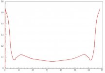
However, the field is far from uniform. This is a pic of two Neo35 bar magnets 60 mm long, 10 mm thick and with a gap of 4 mm (I misread the gap spacing, so everything got simulated at twice the intended size). Most of the field wraps around in free space rather than filling the gap. So efficiency is low and the field is not very uniform as one moves along the gap.
The BM sensor seems to use two magnets polarized along their short axis and in the same orientation, more like Juli's picture.
However, the field is far from uniform. This is a pic of two Neo35 bar magnets 60 mm long, 10 mm thick and with a gap of 4 mm (I misread the gap spacing, so everything got simulated at twice the intended size). Most of the field wraps around in free space rather than filling the gap. So efficiency is low and the field is not very uniform as one moves along the gap.
I have tried various versions, with steel back plates on the outward-facing sides of the magnets and also with steel plates lining the inside.
Either we are misreading the picture or their inductive sensor was just not a smart design.
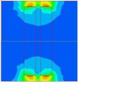
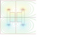
This is actually one of the better versions of the two magnet designs I could come up with. It uses 10 mm steel plates lining a 4 mm gap. The steel plates are about 20 mm long, i.e. somewhat shorter than the Neo35 magnets on the outsides, which are 30 mm long and 6 mm thick.
Either we are misreading the picture or their inductive sensor was just not a smart design.
This is actually one of the better versions of the two magnet designs I could come up with. It uses 10 mm steel plates lining a 4 mm gap. The steel plates are about 20 mm long, i.e. somewhat shorter than the Neo35 magnets on the outsides, which are 30 mm long and 6 mm thick.
Attachments
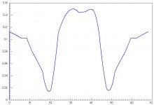
This is a B-field plot. Note higher field and somewhat improved flatness in the center region. The steel plates were centered symmetrically inside the magnets, however, there was a slight assymetry with respect to the simulation boundary which might explain why we are seeing an assymetrical curve.
Attachments
- Status
- This old topic is closed. If you want to reopen this topic, contact a moderator using the "Report Post" button.
- Home
- Loudspeakers
- Multi-Way
- motional feedback (MFB) with inductive sensor