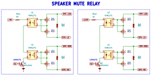
Anyone with experience like to chime in on my speaker relay?
I am looking to use either a 5v or 3.3v supply for powering the VOM1271 in series and would like feedback mostly about any concerns using either voltage.
The nominal forward voltage of both units (1.4 ea) brings the headroom down to 5-2.8=2.2 and 3.3-2.8=0.5 respectively. Would there be any issues with headroom using 3.3v?
Thanks for input
S


The max forward voltage is quoted as 1.6V, so not suitable for using in series with 3.3V,
you'd best put them in parallel for 3.3V with individual current limiting resistors.
you'd best put them in parallel for 3.3V with individual current limiting resistors.
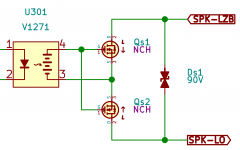
Are you sure this works as intended? It looks as if the internal diodes of the MOSFETs are pointing the same way so one phase is always on, even with the MOSFET off.
If they are not pointing the same way your gate drive only will switch on one MOSFET at the time and the circuit is always off.
Unless I miss something?
Jan
If they are not pointing the same way your gate drive only will switch on one MOSFET at the time and the circuit is always off.
Unless I miss something?
Jan
Are you sure this works as intended? It looks as if the internal diodes of the MOSFETs are pointing the same way so one phase is always on, even with the MOSFET off.
If they are not pointing the same way your gate drive only will switch on one MOSFET at the time and the circuit is always off.
Unless I miss something?
Jan
______
Well spotted, sources should be connected together.
I think is is like this:
If SPK_LZB is positive, the gate of Qs1 is pos wrt the source, so it will conduct, and the diode of Qs2 conducts also.
If SPK-LO is positive, Qs2's gate is also pos wrt its source and Qs2 conducts, and the diode of Qs1 also conducts.
Does that mean that there is always a diode in the circuit in addition to the MOSFET on-resistance?
Jan
Put a 1MEG resistor between pin 3 and 4 of the VOM devices. Without it, the input capacity of the FET’s is slowly charging. First try without this resistor and measure, you will see.
I used two of these photovoltaic devices in parallel to switch on and off IRFP4568 FET’s.
I used two of these photovoltaic devices in parallel to switch on and off IRFP4568 FET’s.
Thanks for the tip..
It couldn't hurt I suppose regardless.
Have you experienced any oscillations using the VOM1271?
Word has it that sometimes there's a need for a resistor on pin 4 if the trace length is longer than a centimetre or so.
It couldn't hurt I suppose regardless.
Have you experienced any oscillations using the VOM1271?
Word has it that sometimes there's a need for a resistor on pin 4 if the trace length is longer than a centimetre or so.
Have not noticed any oscillations.
Here is my pcb layout. Trace lenght pin 4 is only a couple of millimeters.
https://www.diyaudio.com/forums/solid-state/318946-ssr-speaker-protection-15.html#post5842491
Here is my pcb layout. Trace lenght pin 4 is only a couple of millimeters.
https://www.diyaudio.com/forums/solid-state/318946-ssr-speaker-protection-15.html#post5842491
I think is is like this:
If SPK_LZB is positive, the gate of Qs1 is pos wrt the source, so it will conduct, and the diode of Qs2 conducts also.
If SPK-LO is positive, Qs2's gate is also pos wrt its source and Qs2 conducts, and the diode of Qs1 also conducts.
Does that mean that there is always a diode in the circuit in addition to the MOSFET on-resistance?
Jan
i think both mosfets are turned on at the same time.
going through a diode would cause distortion.
I think is is like this:
If SPK_LZB is positive, the gate of Qs1 is pos wrt the source, so it will conduct, and the diode of Qs2 conducts also.
If SPK-LO is positive, Qs2's gate is also pos wrt its source and Qs2 conducts, and the diode of Qs1 also conducts.
Does that mean that there is always a diode in the circuit in addition to the MOSFET on-resistance?
Jan
No, Nigel is right. The MOSFETs both get a positive gate-source voltage and they both can conduct current in both directions.
The only reason why you need two of them in anti-series is because of what happens when they are off. With a single MOSFET you would still get conduction in one half of the cycle due to the MOSFET's drain-bulk diode. With two in anti-series you don't because there are two drain-bulk diodes in anti-series and there is always one in reverse.
Put a 1MEG resistor between pin 3 and 4 of the VOM devices. Without it, the input capacity of the FET’s is slowly charging. First try without this resistor and measure, you will see.
The VOM is capable of 15 micro amps.
At 1 MEG, that would gobble up about 8 micro amps.
Are you sure that it shouldn't be something like 10 MEG?
S
- Home
- Amplifiers
- Solid State
- MOSFET speaker relay using VOM1271

